

Additional Support Information#
All support for this design is through BeagleBoard.org community at BeagleBoard.org forum.
Certifications and export control#
Export designations#
HS: 8471504090
US HS: 8517180050
EU HS: 8471707000
Country of origin: China
Todo
Add the FCC, CE and UKCA status of the assembled board.
Hardware Design#
All BeagleBadge hardware design files are published in the
BeagleBadge repository under the
design/ folder.
File |
Contents |
|---|---|
|
Schematic, revision V1.0 |
|
Board layout |
|
Bill of materials |
|
Gerber artwork and drill files for the 6-layer stackup |
Design files are licensed under the Creative Commons Attribution-ShareAlike 4.0 International License. The upstream documentation is licensed under the MIT License.
Software Updates#
The current demo image and how to write it are in Embedded World 2026 demo image. Updating an installed image is covered in Updating the installed software.
RMA Support#
If you feel your board is defective or has issues, request a Return Merchandise Authorization (RMA) by filling out the form at http://beagleboard.org/support/rma. You will need the serial number and revision of the board.
Todo
Add a photograph showing where the serial number and revision are printed on the board.
Getting Help#
If you need up to date troubleshooting techniques, post your questions on the BeagleBoard.org forum.
Issues with the hardware design itself can be raised on the BeagleBadge issue tracker.
Known gaps and open questions#
These points are not yet documented or not yet confirmed. Each links to the section where it will be filled in.
Topic |
Gap |
Where it appears |
|---|---|---|
Weight |
Not yet measured. |
|
GPIO numbers |
Linux GPIO chip and line numbers for the expansion header pins. |
Change History#
This section describes the change history of this document and board. Document changes are not always a result of a board change. A board change will always result in a document change.
Document Change History#
Rev |
Changes |
Date |
By |
|---|---|---|---|
0.0.1 |
Initial BeagleBadge documentation |
August 2026 |
Deepak Khatri |
0.0.2 |
All 25 schematic sheets embedded and annotated, board revision history added from schematic sheet 1 |
September 2026 |
Deepak Khatri |
Board Changes#
The authoritative board revision history is printed on sheet 1 of the schematic, which is reproduced at Table of contents and revision history. It is summarised below. Also check the issues list in the BeagleBadge repository.
Rev |
Date |
Main modifications |
|---|---|---|
Rev A |
14 October 2025 |
Initial release. |
V0.3 |
20 October 2025 |
Capacitor withstand voltage raised to 2x or higher. AND gate schematic symbol
corrected. Switch control added to the power monitoring ADC. |
V0.4 |
24 October 2025 |
|
V0.5 |
28 October 2025 |
Power supply selection added for the IMU. |
V0.6 |
29 October 2025 |
|
V0.7 |
5 November 2025 |
Sheet 8: |
V1.0 |
25 April 2026 |
Sheet 5: |
V1.0 |
28 July 2026 |
|
Rev V1.0#
The production release. Schematic BeagleBadge_V1.0_SCH_260728.pdf dated
28 July 2026, board file BeagleBadge_V1.0_260826.brd dated 26 August 2026, on a
6-layer 1.6mm PCB.
Three decisions in this revision change what a user can expect from the board and are worth reading before you buy or design against it:
eMMC is not populated. The footprint is there. The device is not. See eMMC footprint.
The GPIO expansion pads are 1.8V, settled in V0.7. See GPIO expansion header.
Charging is limited to 430mA with a 45 degrees C NTC cutoff, which sets how quickly a BL-5C cell recharges. See Battery charging and power path.
Mechanical Details#
Board size, PCB stackup, mounting and the ePaper module outline are tabulated in Dimensions and weight.
Pictures#
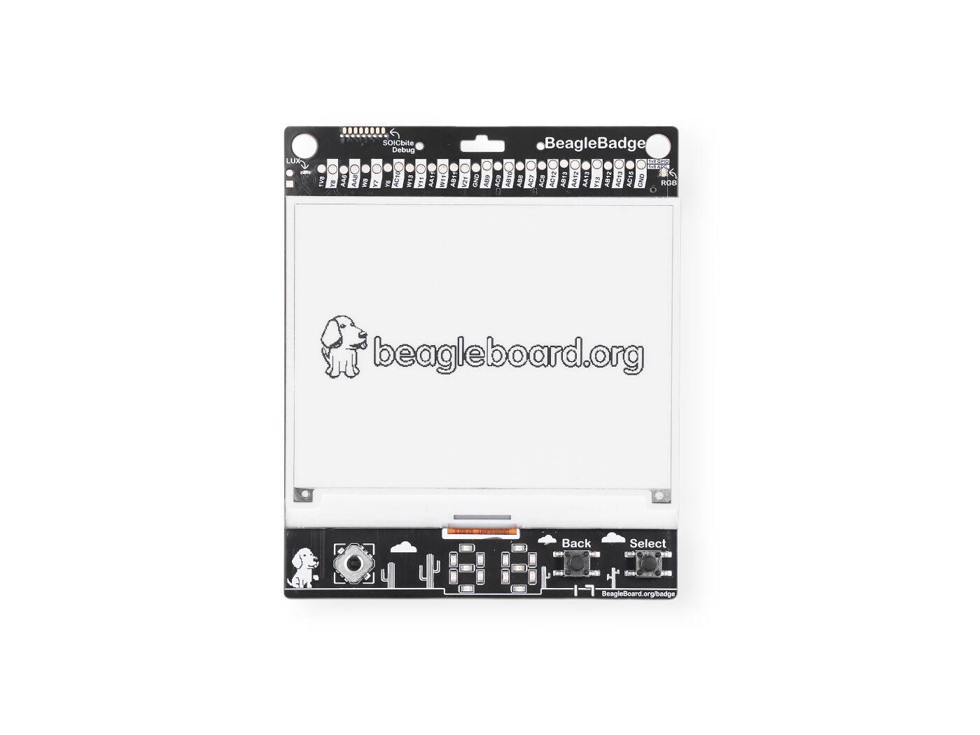
Fig. 311 BeagleBadge front#
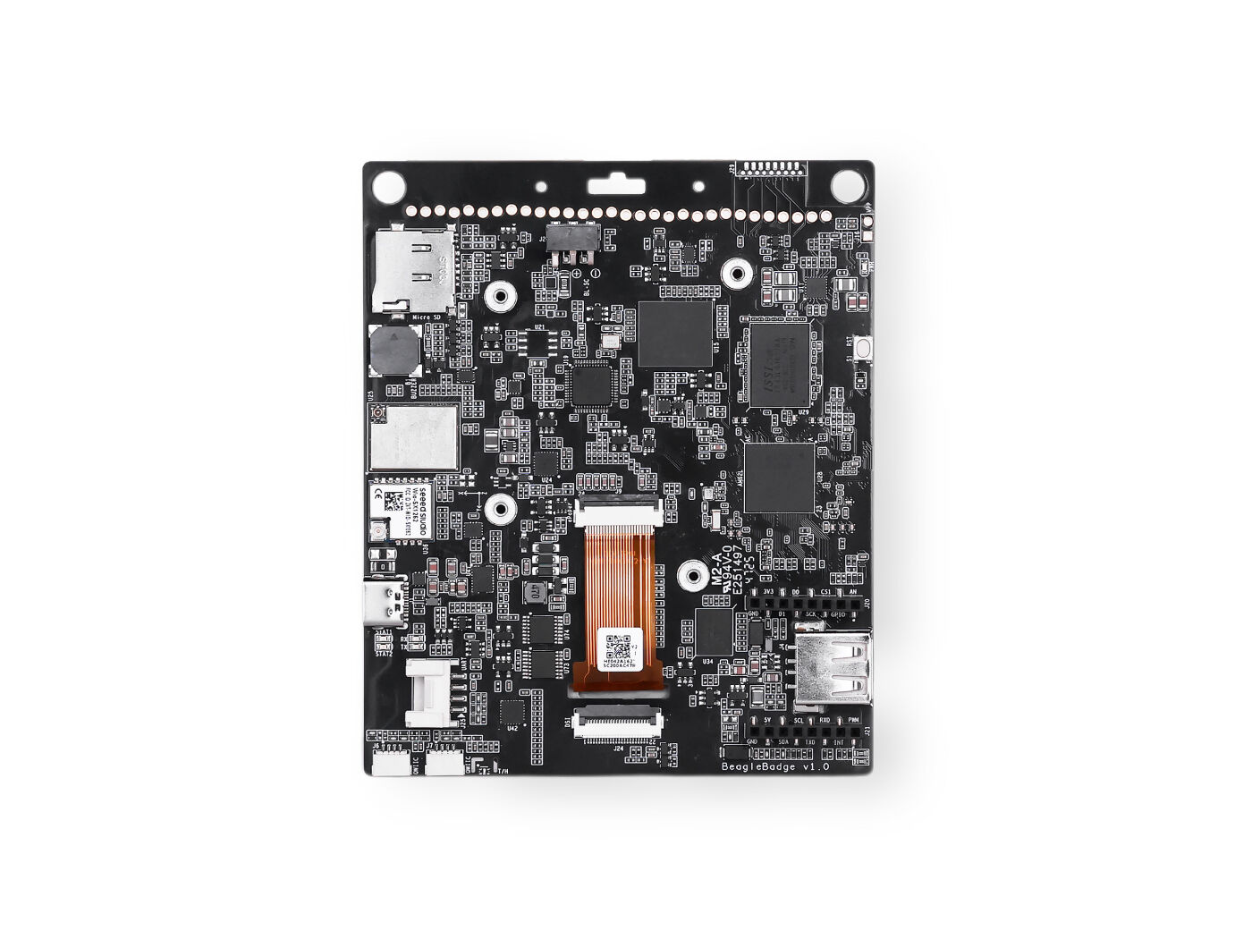
Fig. 312 BeagleBadge back#
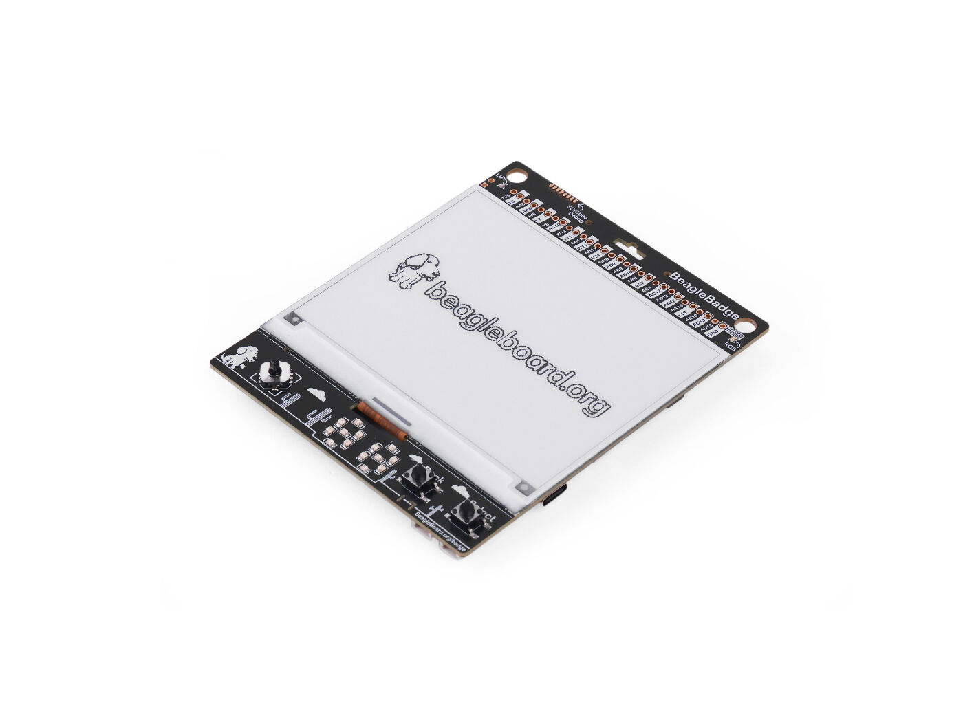
Fig. 313 BeagleBadge front at an angle#
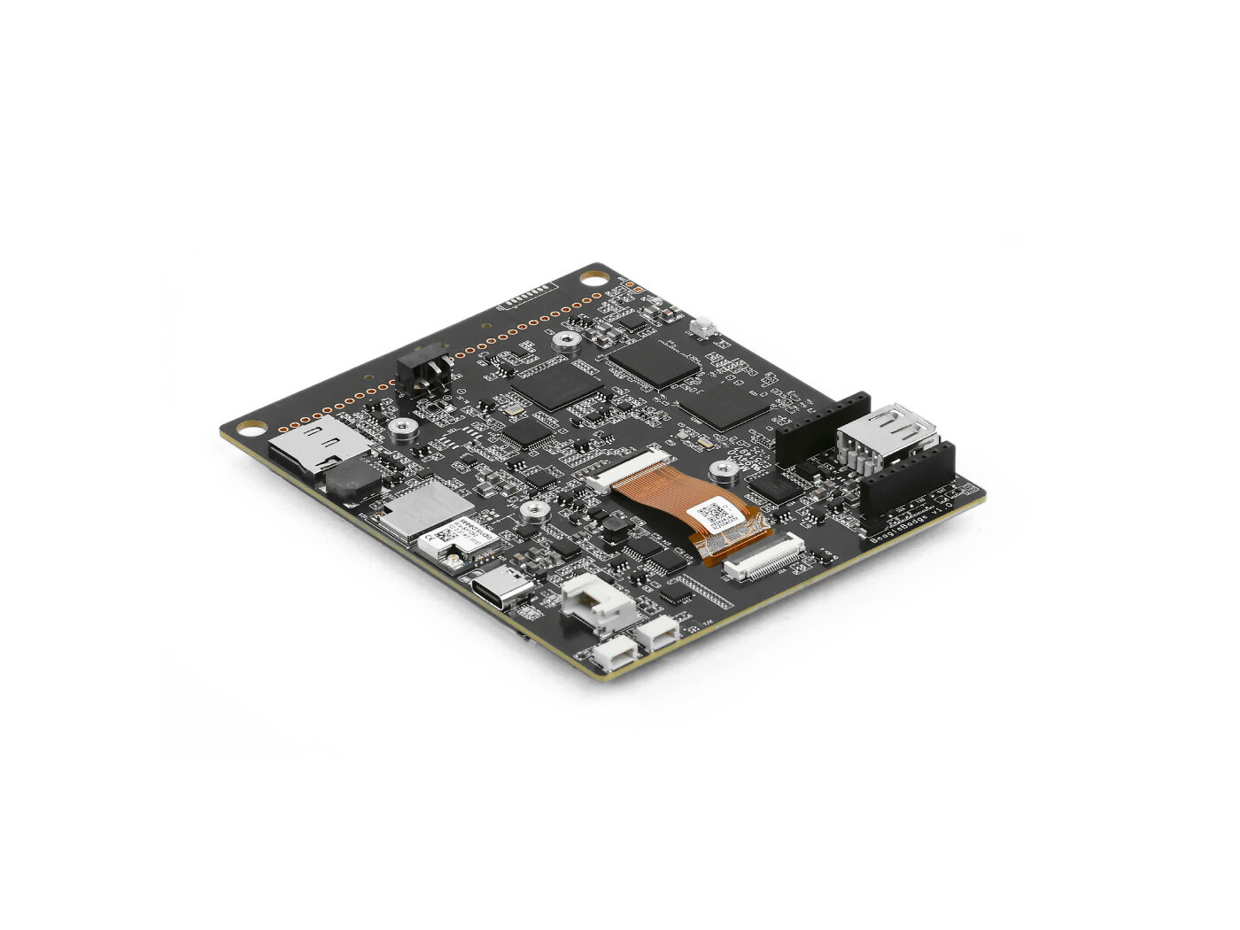
Fig. 314 BeagleBadge back at an angle#