

Introduction#
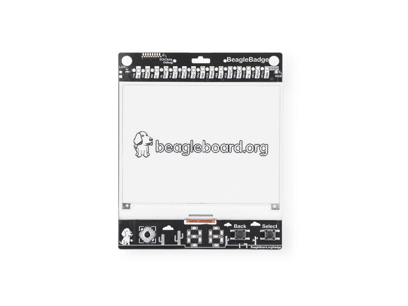
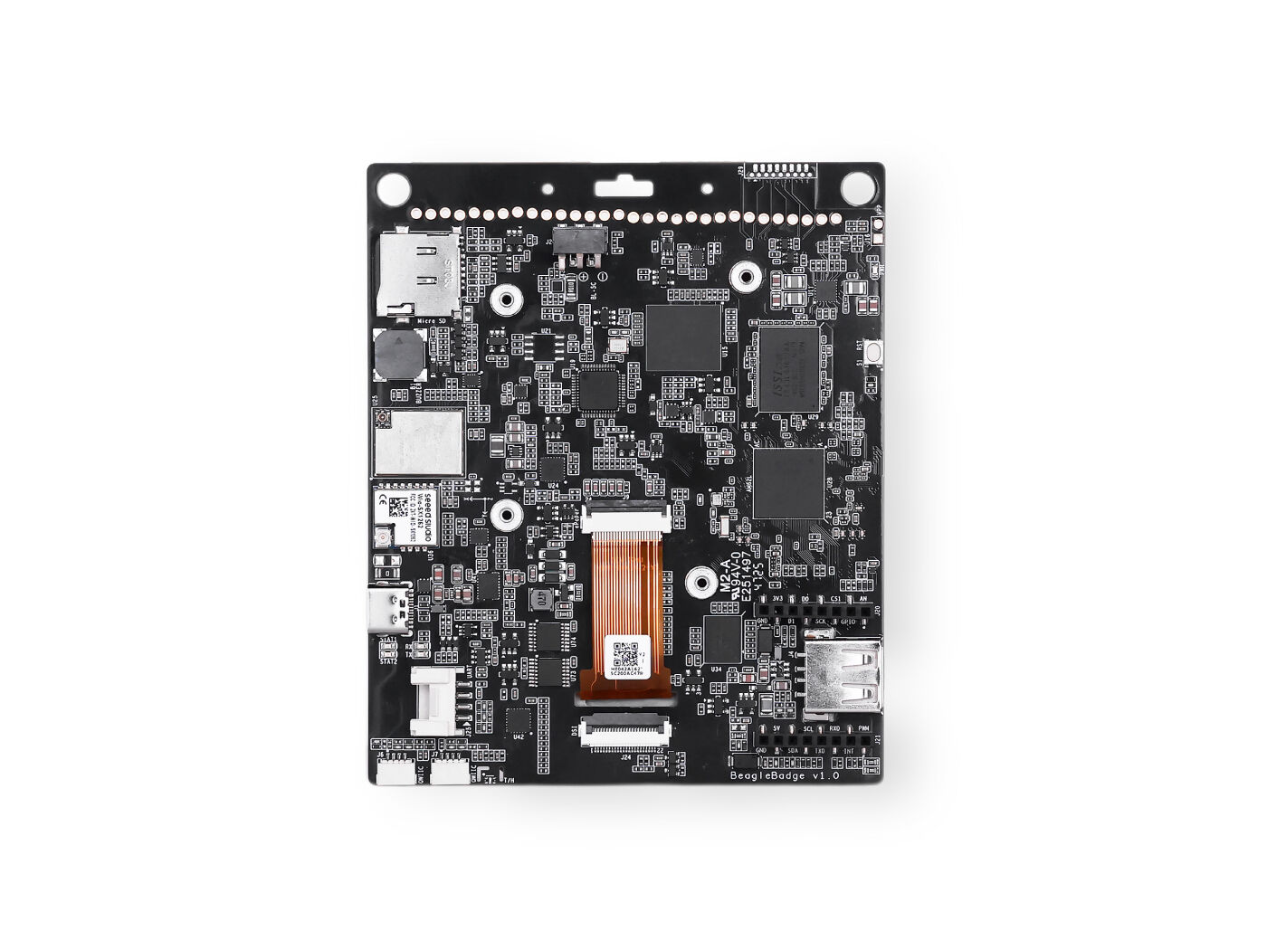
BeagleBadge brings a new vision to wearable computing with e-ink display by combining built-in sensing with broad expansion flexibility. Built around the low-power Texas Instruments AM62L32 SoC and a 4.2 inch ePaper display. BeagleBadge pairs Wi-Fi 6, Bluetooth Low Energy 5.4, and LoRaWAN wireless connectivity. It has on-board 4-way joystick, tactile buttons, an RGB LED, and dual 7-segment displays for a complete human-machine interface out of the box. An onboard ambient light sensor, an IMU for precise position & orientation feedback, and temperature & humidity monitoring let you design intuitive, context-aware interactions. Beyond its core features, two QWIIC connectors along with Grove and mikroBUS headers unlock thousands of additional sensors, actuators, pulse oximeters, UV spectroscopy, fingerprint readers, GPS, haptics, and audio applications. That modularity makes BeagleBadge a versatile innovation platform that enables rapid prototyping, research, and real-world solutions in health, environment, and human-machine interfaces, while remaining practical, scalable, and accessible to all.
|
|
BeagleBadge Features and Specifications#
This section provides an overview of the key features and specifications of the BeagleBadge board, highlighting its built-in sensors and expansion capabilities. The table below summarizes the main features and their descriptions, showcasing the versatility and potential applications of the BeagleBadge platform.
Category |
Item |
Specification |
|---|---|---|
Processor and memory |
SoC |
Texas Instruments AM62L32, low-power SoC with display for IoT, HMI and general-purpose applications |
CPU |
Dual-core Arm® Cortex®-A53 processor @ 1.25GHz |
|
RAM |
256MB LPDDR4 (2Gb, 128M x 16bit) 1600MHz 3200Mbps |
|
Flash/non-volatile |
256Mb OSPI flash |
|
32Kb EEPROM |
||
Networking |
Wi-Fi & Bluetooth |
802.11ax Wi-Fi 6 (2.4GHz) and Bluetooth Low Energy (BLE) 5.4 |
via BeagleBoard.org BeagleMod BM3301-1216 (TI CC3301), IPEX Gen 4 (MHF4) connector |
||
LoRaWAN |
Wio SX1262 module (u.FL connector) |
|
Built-in sensors |
Sensors |
1x IMU sensor |
1x Ambient light sensor |
||
1x Temperature & humidity sensor (not populated) |
||
User interface |
Input |
1x Reset button |
1x 4-way joystick button with press |
||
2x Tactile buttons (Back and Select) |
||
Output |
1x Passive buzzer |
|
1x RGB status LED |
||
2x 7-segment LED displays |
||
Battery interface |
Battery |
Battery management with fuel gauge monitoring |
1x BAT connector for BL-5C |
||
Expansion/connectors |
Display |
Support 4.2 inch ePaper via 24-pin FPC connector |
MIPI DSI connector for LCD displays |
||
Power & debug |
USB Type-C for power input and debug |
|
Ecosystem |
1x mikroBUS connector |
|
2x QWIIC connector |
||
1x Grove connector |
||
Host & storage |
1x USB 2.0 Type-A host |
|
1x Micro-SD socket |
||
Software |
Base ports |
Linux and Zephyr base ports with mainline roadmap |
Libraries |
LVGL and MicroPython libraries for interactive ePaper display |
|
Examples |
App store for programming examples |
|
Messaging |
Meshtastic and ActivityPub integration for seamless off-grid messaging |
Board Component Locations#
The figures below locate each key component on the front and back of the board, with a table naming what each one does.
Todo
Replace both photographs with v1.0 board images. The current ones predate the Power
button (S2 on schematic sheet 20). Label the
Power button and the two GPIO expansion headers in the
new annotations.
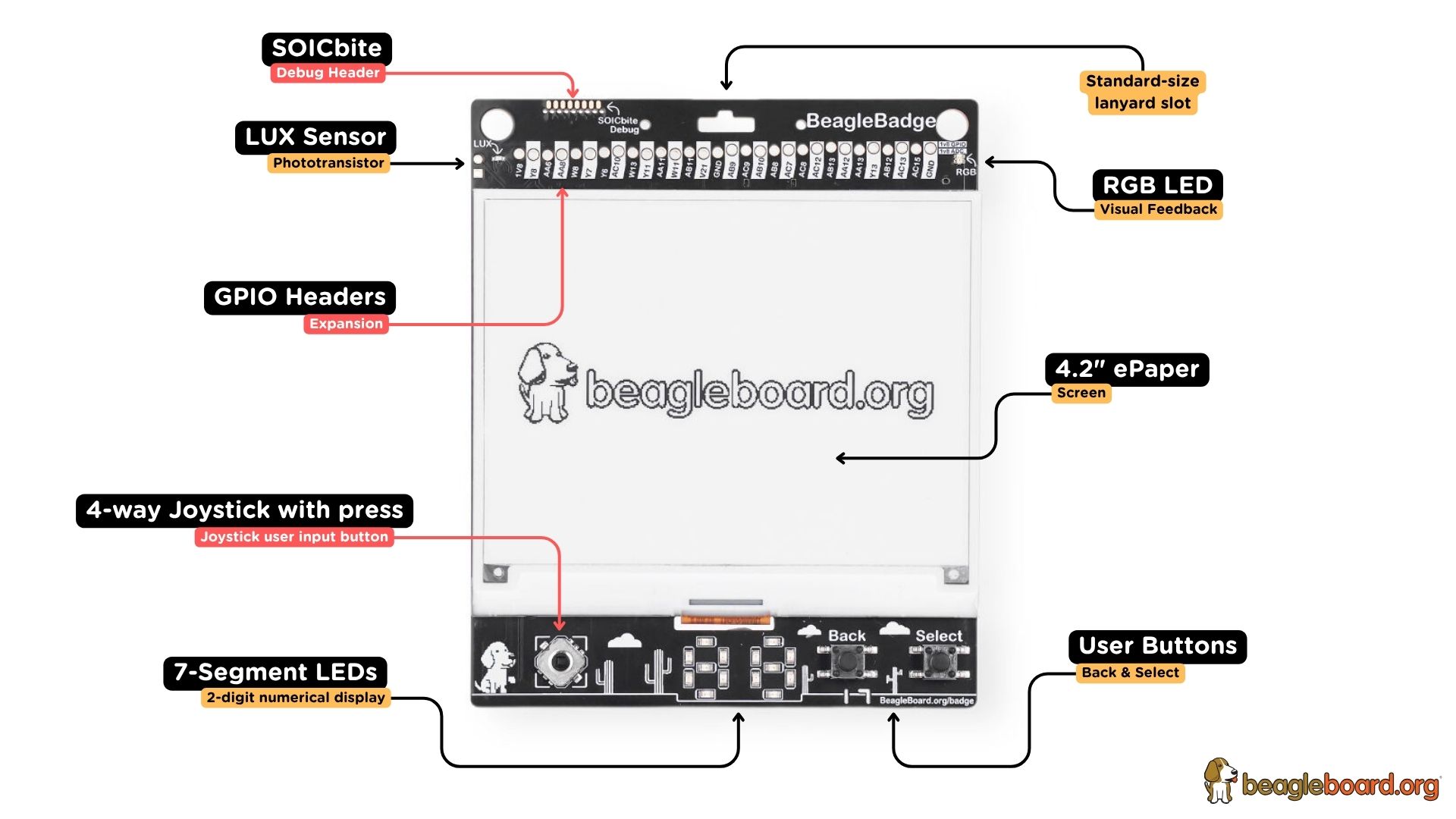
Fig. 309 BeagleBadge board front components location#
Feature |
Description |
|---|---|
4.2” ePaper |
400 x 300 black-and-white ePaper screen, the primary display |
LUX sensor |
Ambient light phototransistor |
RGB LED |
User controllable RGB LED for visual feedback |
7-segment LEDs |
2-digit numerical display |
4-way joystick |
Joystick user input button with centre press |
User buttons |
Back and Select tactile buttons |
GPIO headers |
1.8V GPIO and ADC expansion header along the top edge |
SOICbite |
Debug header, accessed with a standard SOIC test clip |
Lanyard slot |
Standard-size lanyard slot |
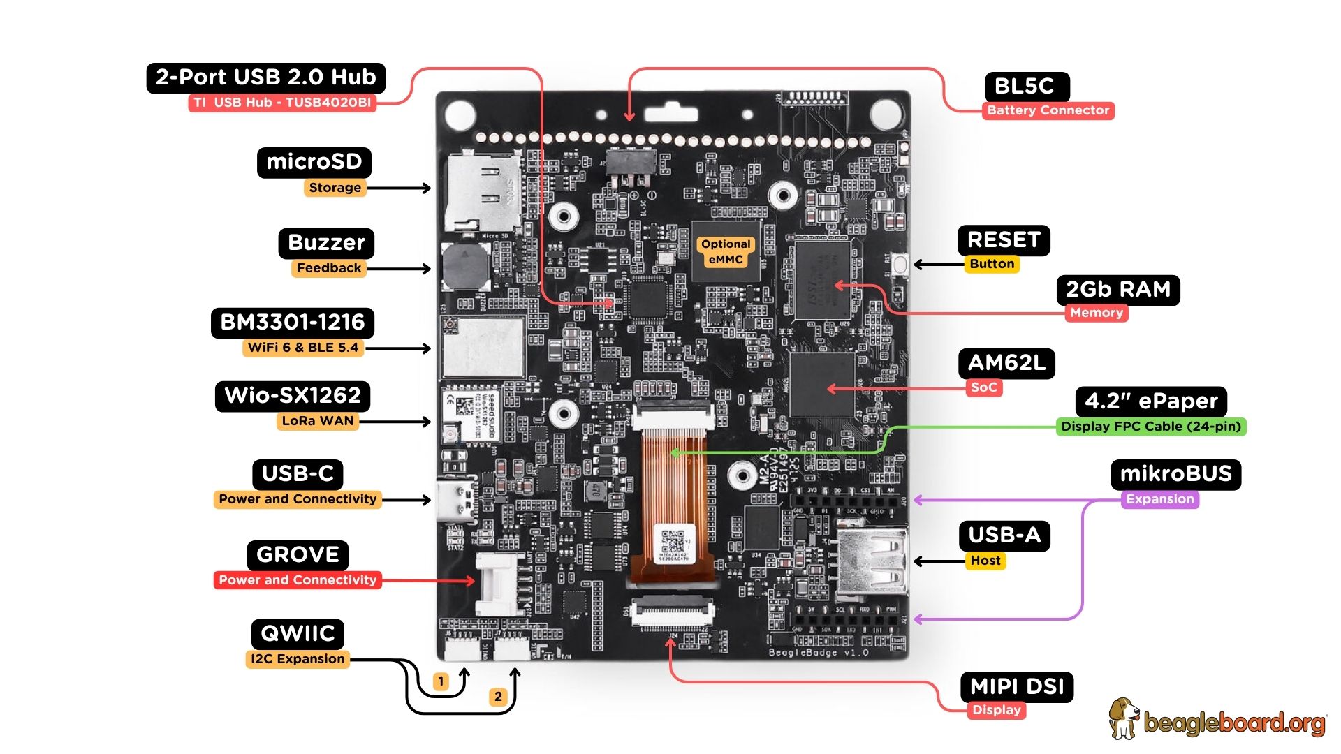
Fig. 310 BeagleBadge board back components location#
Feature |
Description |
|---|---|
AM62L |
Texas Instruments AM62L32 SoC, dual Arm Cortex-A53 at 1.25GHz |
256MB RAM |
LPDDR4 at 1600MHz, a 2Gb (128M x 16) device |
Optional eMMC |
eMMC footprint, not populated on v1.0. See eMMC footprint |
BM3301-1216 |
BeagleMod module providing Wi-Fi 6 and BLE 5.4 |
Wio-SX1262 |
LoRaWAN module |
2-port USB 2.0 hub |
Texas Instruments TUSB4020BI |
microSD |
microSD card socket for storage |
USB-C |
Power and connectivity, also carries the serial debug console |
USB-A |
USB 2.0 Type-A host port for peripherals |
mikroBUS |
mikroBUS expansion socket for MikroElektronika Click boards |
QWIIC |
Two I2C expansion connectors, marked 1 and 2 |
Grove |
Grove expansion connector |
MIPI DSI |
FPC connector for an LCD display |
4.2” ePaper FPC |
24-pin FPC connector for the ePaper display cable |
BL5C |
Battery connector for a BL-5C cell |
RESET |
Reset button |
Buzzer |
Passive buzzer for audible feedback |