Design and Specifications#
Work in progress
Todo
Add details about all the schematic sections.
If you want to know how BeagleY-AI is designed and the detailed specifications, then this chapter is for you. We are going to attempt to provide you a short and crisp overview followed by discussing each hardware design element in detail.
Tip
For board files, 3D model, and more, you can checkout the BeagleY-AI repository on OpenBeagle.
Block Diagram and Overview#
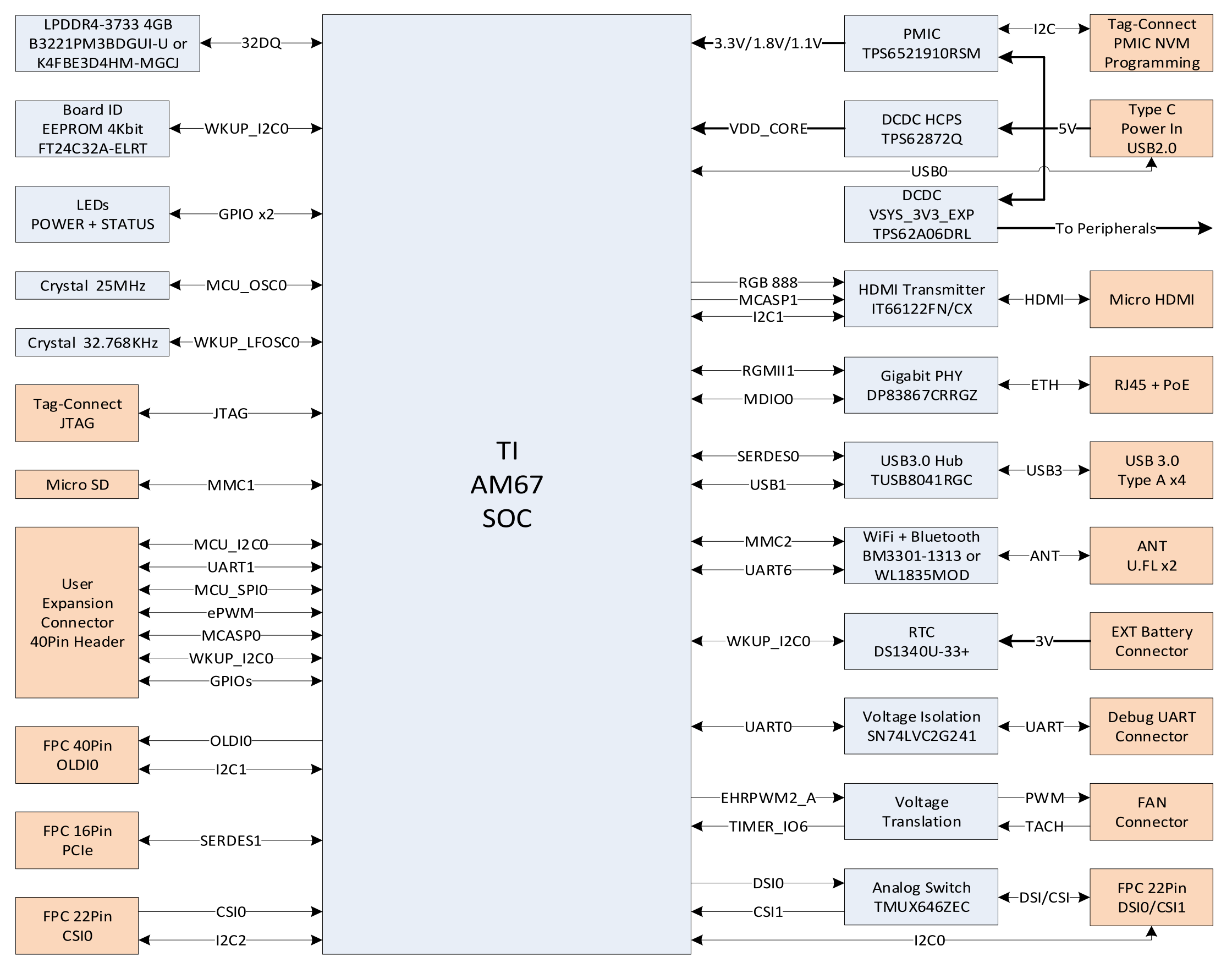
Fig. 47 BeagleY-AI block diagram#
Processor#
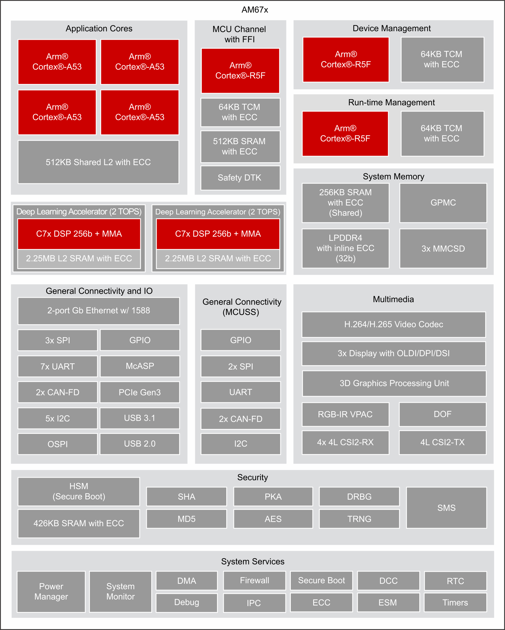
Fig. 48 AM67A block diagram#
The AM67A processor from Texas Instruments is a highly integrated SoC with an Automotive pedigree. It may be referenced by TI documentation by it’s superset J722s/TDA4AEN.
It’s primary compute cluster revolves around 4xARM Cortex-A53 Cores running at 1.4Ghz.
An MCU subsystem consisting of an ARM Cortex-R5F running at up to 800Mhz is also available for user applications and is especially useful for real-time IO applications.
For very advanced users, two additional R5 cores are also present, but they are normally reserved for Device and Run-time Management of the SoC typically.
2x C7x DSPs with MMA support are intended for use as Deep Learning Accelerators for things like AI Vision, with up to 2TOPS each.
An Imagination BXS-4-64 GPU rounds out the compute cluster, with a dedicated video encoder/decoder available for multimedia tasks.
The SoC features advanced high speed connectivity, including USB3.1, PCIe and more.
Secure Boot is also available with the ability burn One-Time-Programmable (OTP) eFUSES by energizing the VPP test pads.
Boot Modes#
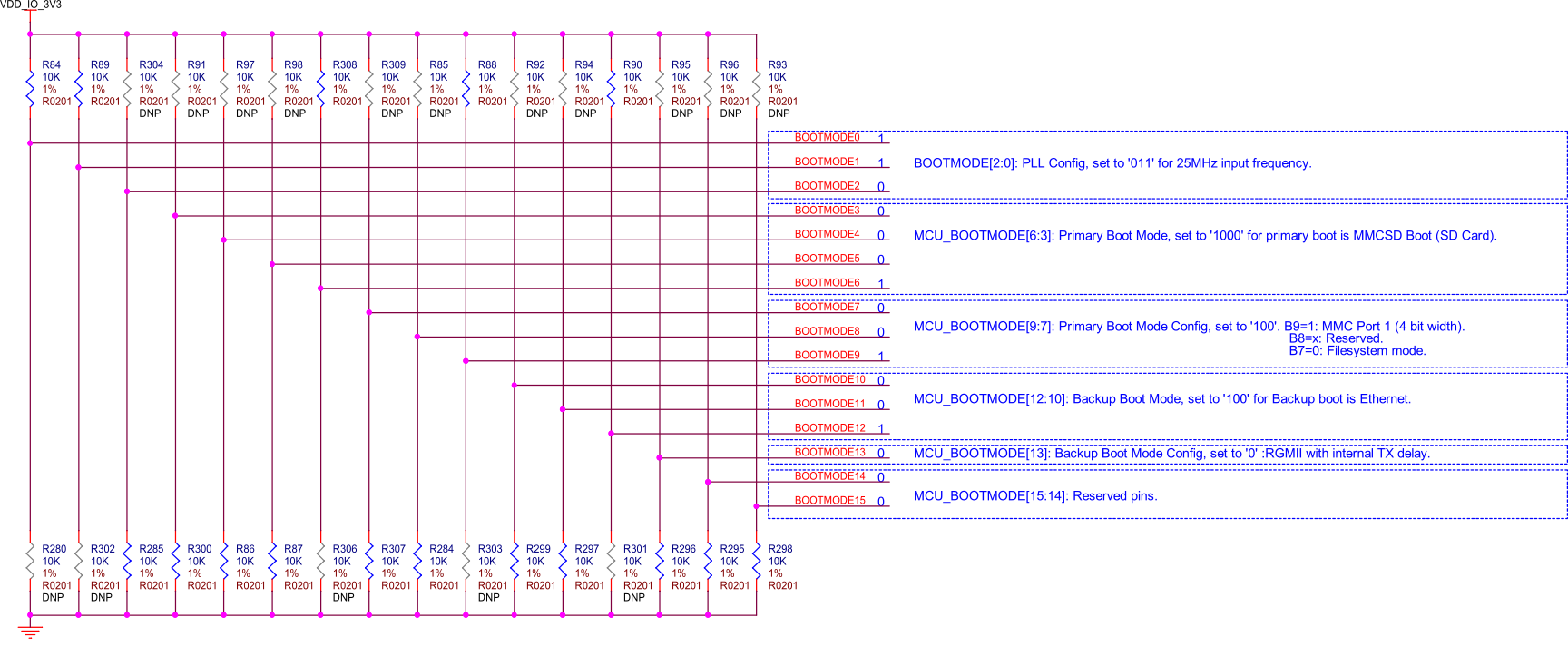
Fig. 49 BeagleY-AI boot modes#
The default boot mode for BeagleY-AI is the SD Card Interface. If no SD card is present, the BootROM on the AM67A SoC is going to try booting from Ethernet.
It is also possible to load U-Boot from the SD card and then load your main file system from another source, such as Booting from NVMe Drives.
Power#
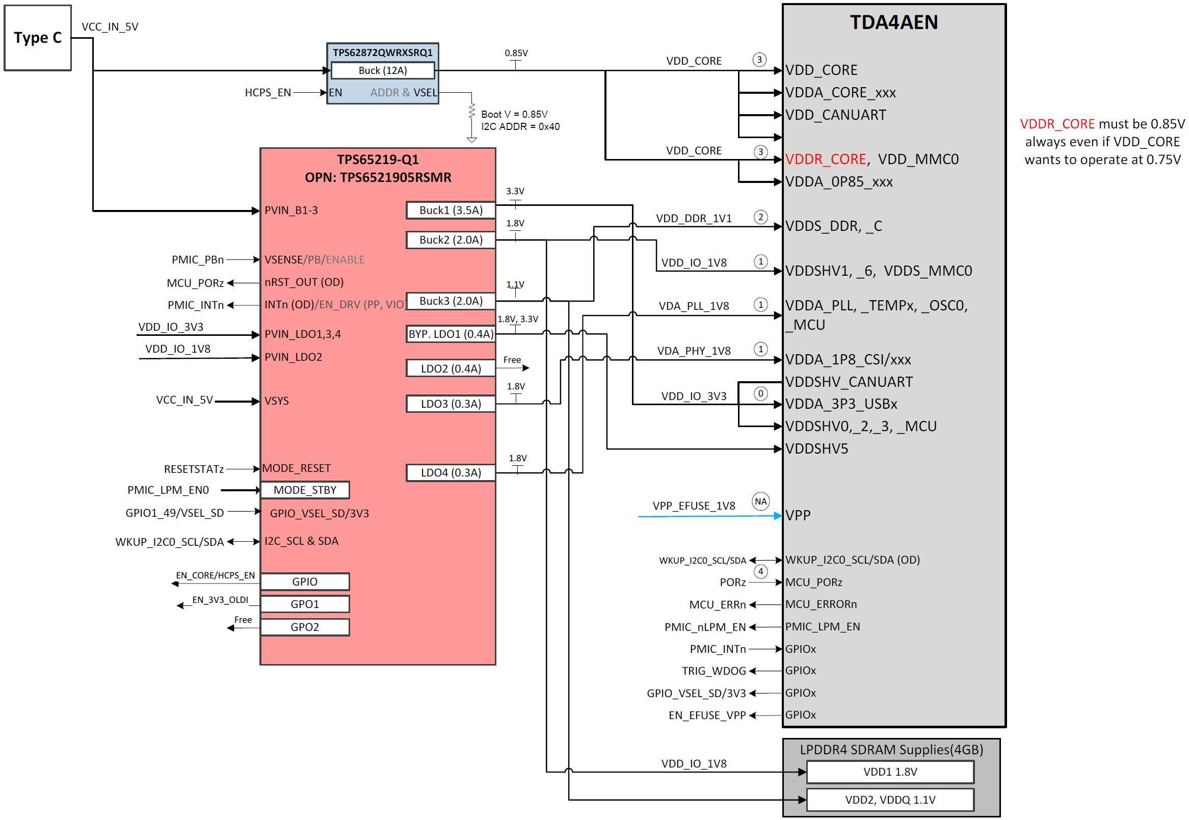
Fig. 50 BeagleY-AI power distribution network#
BeagleY-AI’s power architecture is split between the TPS65219 PMIC which handles the main logic rails and a dedicated TPS62872 high current buck regulator for the SoC core rail which defaults to 0.85V on boot.
Both PMIC and VDD_CORE regulators are highly configurable but will boot the board to “sane” defaults out of box. For advanced users, it is possible to adjust both the VDD_CORE rail as well as IO rails (voltages, timings, behavior, etc.) for applications such as low power modes where you may want to trade clock speeds for power efficiency by running the SoC Core at 0.75V for example. Be careful, as changes here could result in unexpected behavior, the board not booting or even hardware damage, so tread carefully.
Note
At the time of writing, dynamic voltage switching is not supported by the AM67A SoC.
Clocks and Resets#
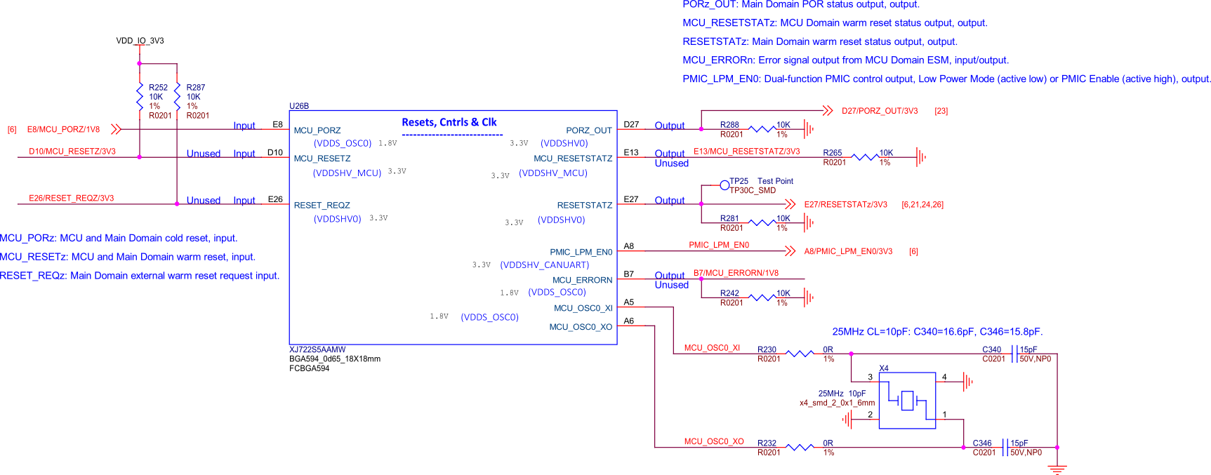
Fig. 51 BeagleY-AI SoC Reset, Cntrls, and Clk#
BeagleY’s main clock source is a 25Mhz Crystal Oscillator connected to MCU_OSC0 pins.
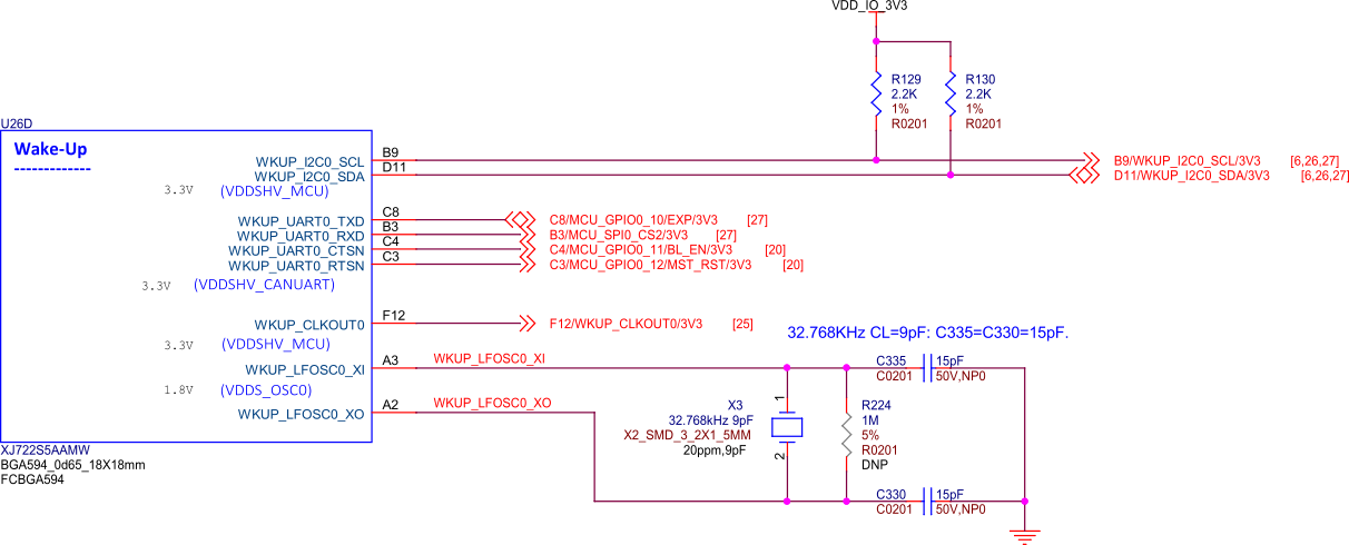
Fig. 52 BeagleY-AI wkup reset cntrls osc#
A 32.768Khz “Slow Clock” Crystal is used on the WKUP_LFOSC0 domain.
USB-C Power/Data Port#
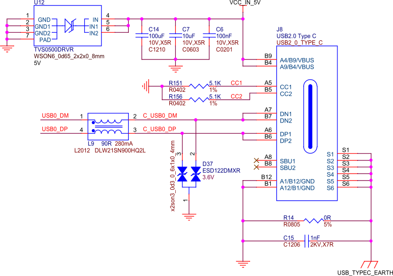
Fig. 53 BeagleY-AI USB-C#
The board is primarily intended to be powered via USB-C. PD Power negotiation is not done dynamically but rather by tying the CC lines to GND via 5.1KΩ resistors to indicate to the PD Source that the device requires 5V 3A. Using USB-PD power supplies rated for higher wattages is safe as they will always negotiate to the 5V 3A requested by the board.
The USB-C port is configured by default to also show up as a USB2.0 Device which exposes a serial console, ethernet gadget (for connection sharing) as well as MTP (Flash Drive) so that only one cable is required to use the board. A Type-C to Type-C cable and avoiding un-powered USB hubs is recommended due to the board’s power consumption requirements. Inadequate behavior may result in brownouts/resets or other unexpected behavior.
PMIC#
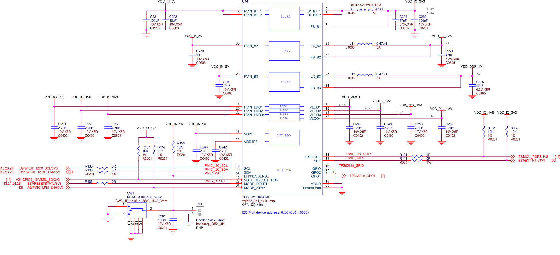
Fig. 54 BeagleY-AI PMIC#
HCPS (High Current Power Stage)#
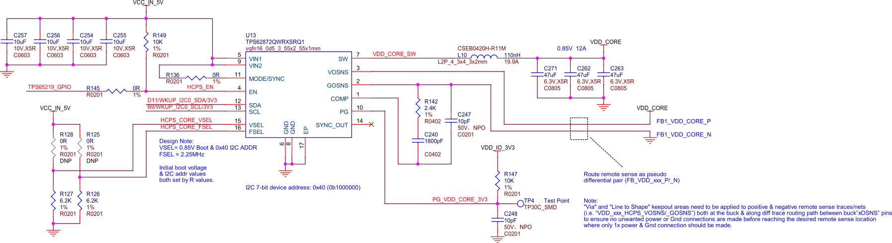
Fig. 55 BeagleY-AI VDD core High Current Power Stage (HCPS)#
Analog Rail Decoupling#
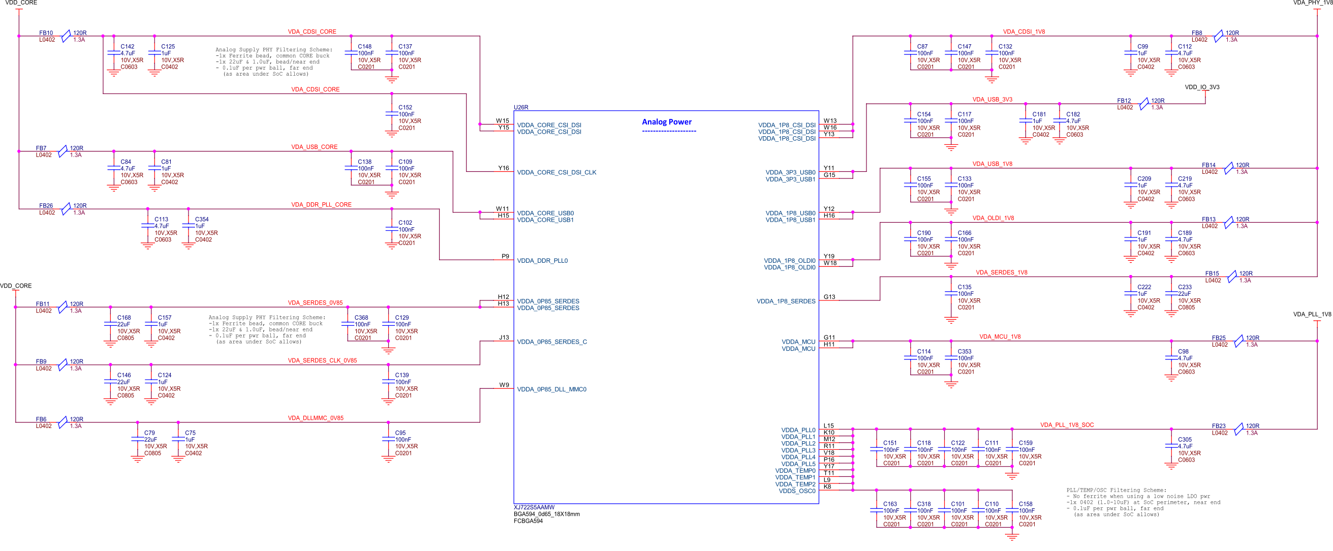
Fig. 56 BeagleY-AI SoC analog power rail decoupling capacitors#
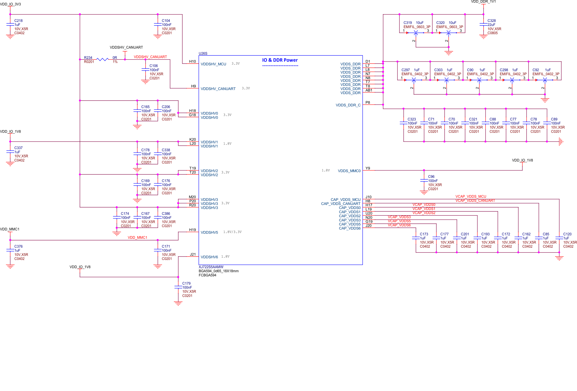
Fig. 57 BeagleY-AI AI SoC IO and DDR decoupling capacitors#
Digital Rail Decoupling#
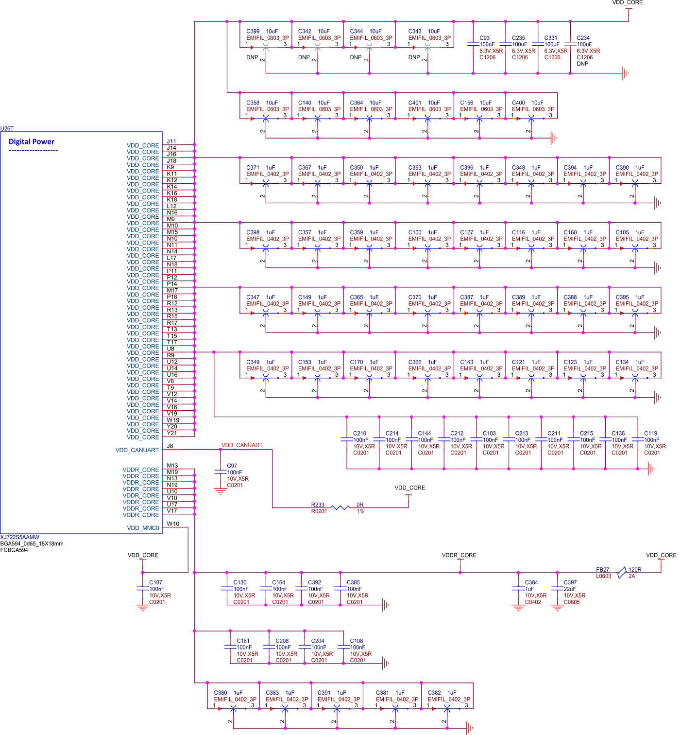
Fig. 58 BeagleY-AI SoC VDD & VDDR_CORE decoupling capacitors#
Note
Other power sections are nested within their specific interface section.
LDOs#
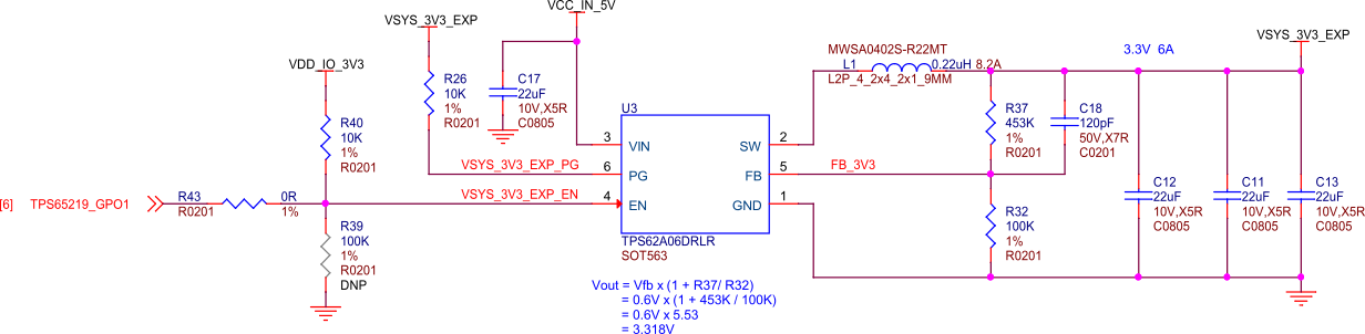
Fig. 59 BeagleY-AI VSYS 3V3#
While the 3.3V VDD_IO rail is provided by the PMIC, the actual “high current” VSYS 3.3V rail used on the expansion header and elsewhere in the system is provided by a discrete TPS62A06DRLR regulator.
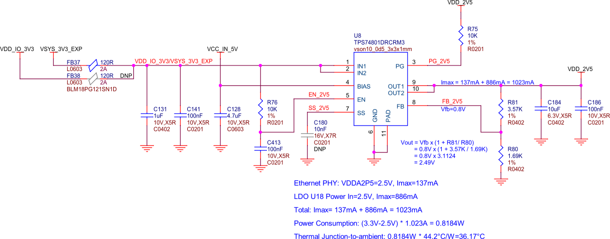
Fig. 60 BeagleY-AI ethernet power 3V3 to 2V5#
The 2V5 Rail used by the Ethernet PHY is generated a discrete TPS74801 regulator. This regulator is fed by the 3V3 VSYS regulator.
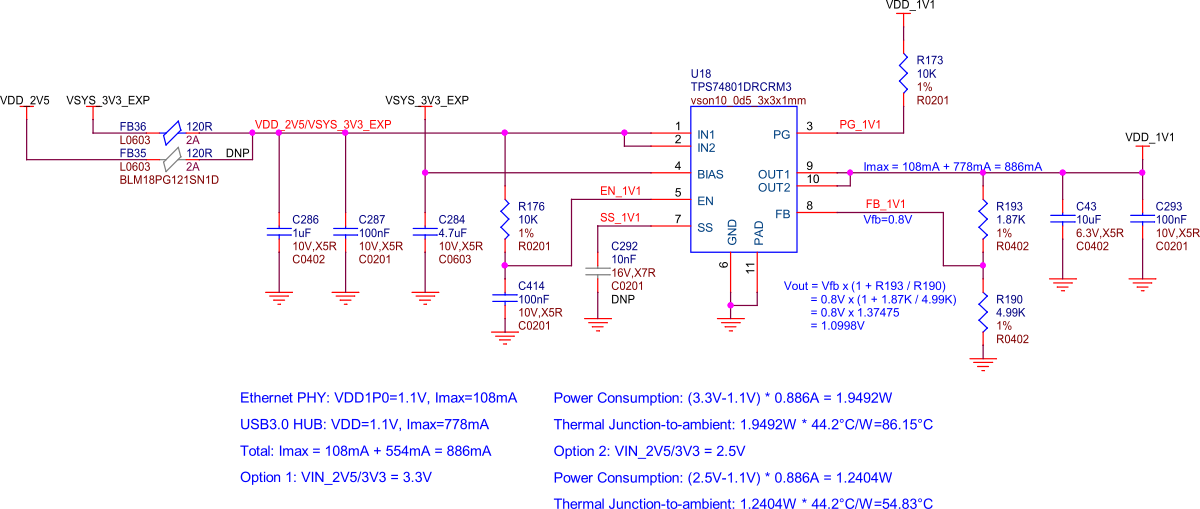
Fig. 61 BeagleY-AI 3V3/V5 to 1V1 LDO#
The 1V1 Rail used by the PHY and USB 3.1 Hub is generated a discrete TPS74801 regulator. By default, this regulator is fed by the 3V3 VSYS regulator previously discussed.
Memory#
RAM (LPDDR4)#
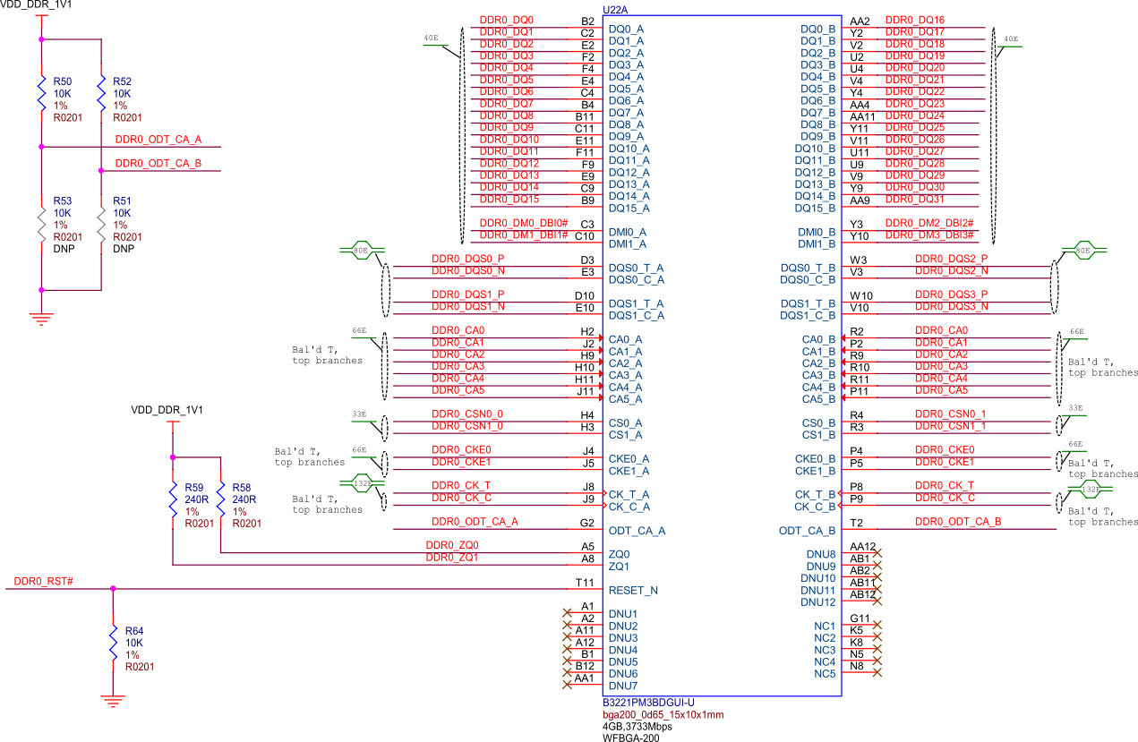
Fig. 62 BeagleY-AI DDR#
BeagleY-AI has 4GB of Kingston x32 LPDDR4 Memory.
Todo
Add Final DDR Part Number
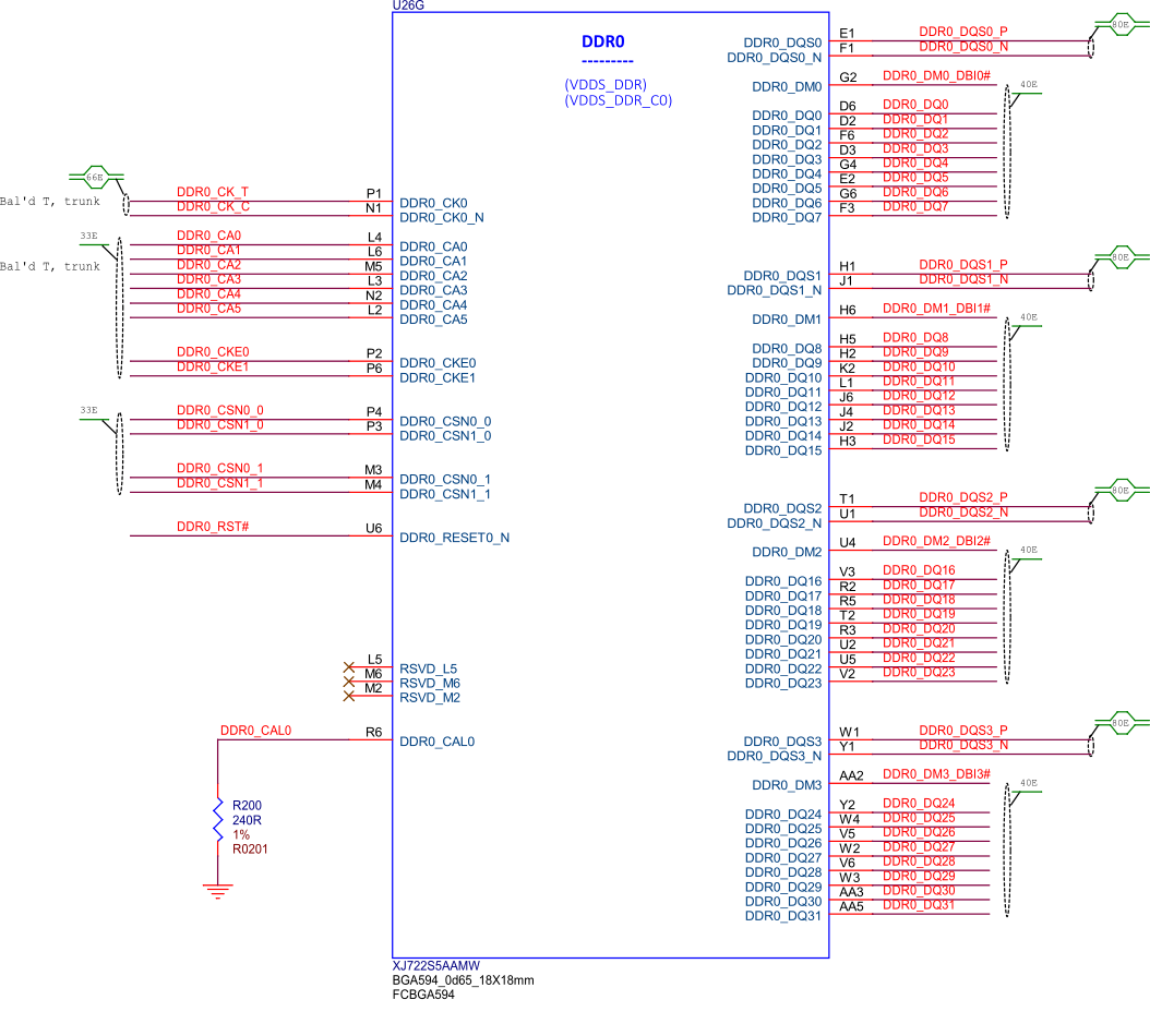
Fig. 63 BeagleY-AI SoC DDR0 connections#
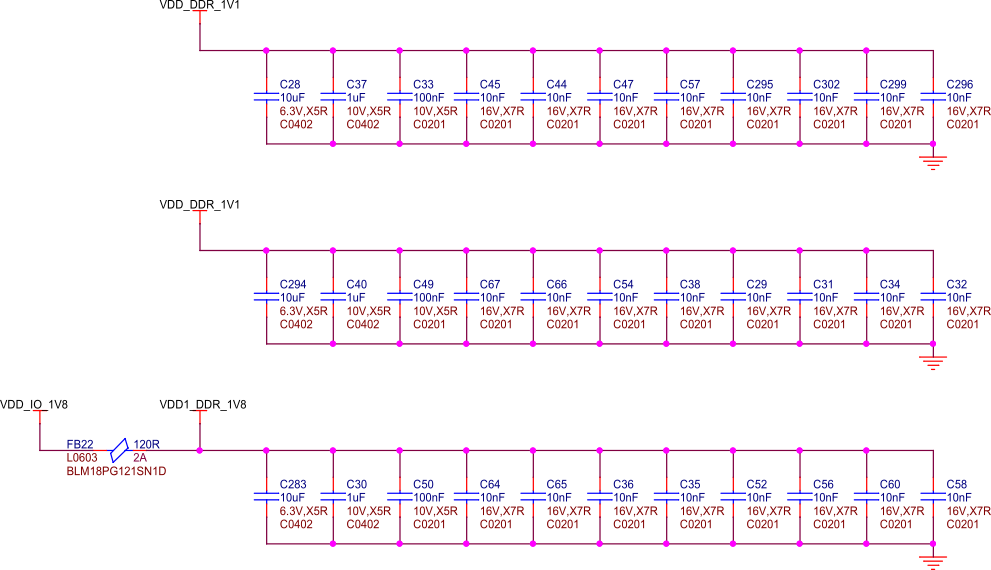
Fig. 64 BeagleY-AI DDR caps#
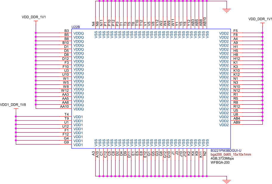
Fig. 65 BeagleY-AI DDR power#
EEPROM#
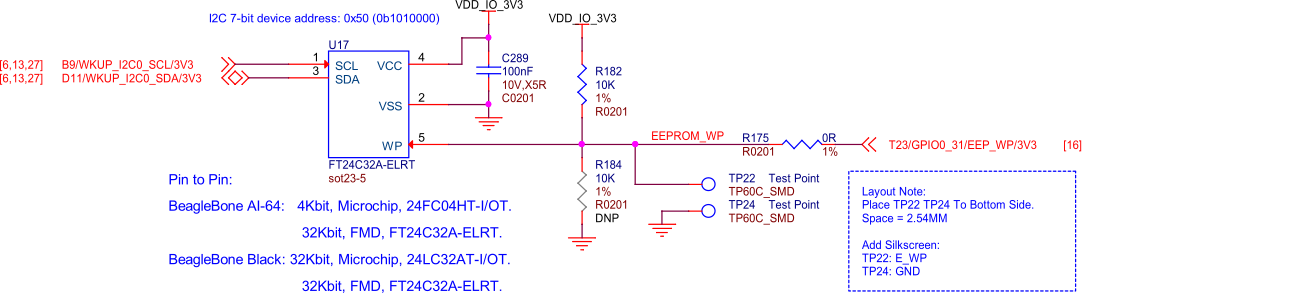
Fig. 66 BeagleY-AI board id eeprom#
BeagleY-AI features an on-board FT24C32A 32Kbit I2C EEPROM for storing things like board information, manufacture date, etc.
Todo
Add details about specific EEPROM contents and formatting.
microSD Card#
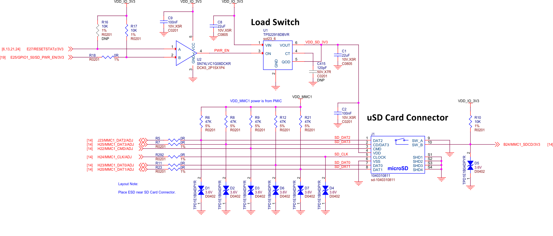
Fig. 67 BeagleY-AI microSD card interface#
The microSD card is the primary boot interface for BeagleY-AI, it corresponds to the MMC1 interface on the AM67A SoC.
To enable UHS-1 SD card functionality (and speeds!), a load switch is provided which allows the SoC MMC1 PHY to switch the SD Card IO voltage to 1.8V.
Todo
Explain UHS-1 in more detail and add link to TRM for boot modes and resistor swap options for advanced users.
General Expansion#
40pin Header#
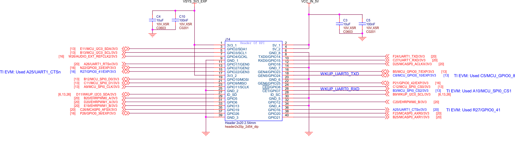
Fig. 68 BeagleY-AI user expansion connector#
BeagleY-AI features a 40-pin GPIO Header which aims to enable compatibility with a lot of existing Raspberry Pi HAT add-on boards. See pinout.beagleboard.io for a more comprehensive view of the 40 pin GPIO header, available pin functions and tested accessories!
Todo
Add link to docs on building expansion accessories.
I2C#
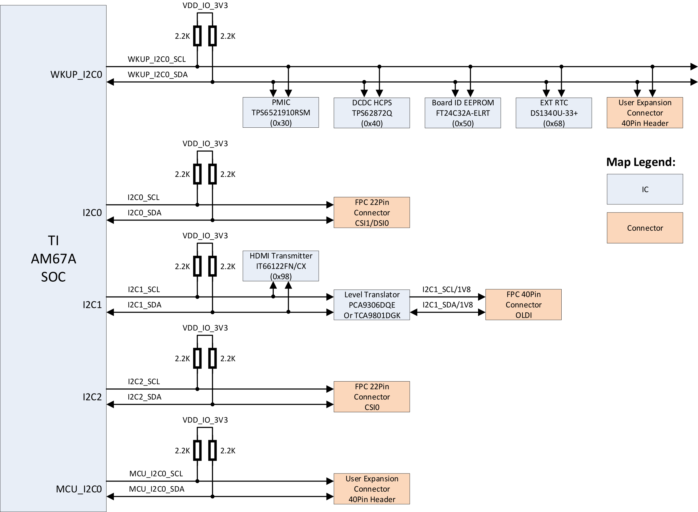
Fig. 69 BeagleY-AI I2C tree#
By default, 5 different I2C interfaces are exposed, all of which feature external 2.2KΩ pull-up resistors. 3 of the interfaces are used by the CSI, DSI and OLDI ports for Cameras & Displays. The remaining 2 ports are exposed on the 40pin GPIO expansion connector.
The MCU_I2C0 interface is intended as the primary external I2C interface for BeagleY-AI and matches physical pins 3 and 5 of the header. Most HATs will use these pins.
While WKUP_I2C0 is also exposed on the 40pin Header (physical pins 27 & 28), that bus is shared with several on-board devices, namely the PMIC, VDD_CORE regulator, Board ID EEPROM and RTC. As such, it is highly advisable to leave these pins unused unless you are sure you know what you are doing. These pins are normally only pinned out as a “HAT EEPROM detect” for RPi HATs that provide such functionality (of which there are very few)
See pinout.beagleboard.io/pinout/i2c for a more visual explanation.
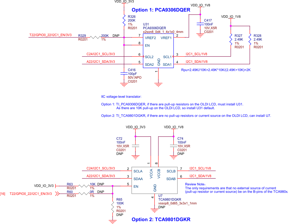
Fig. 70 BeagleY-AI voltage level translator#
USB#
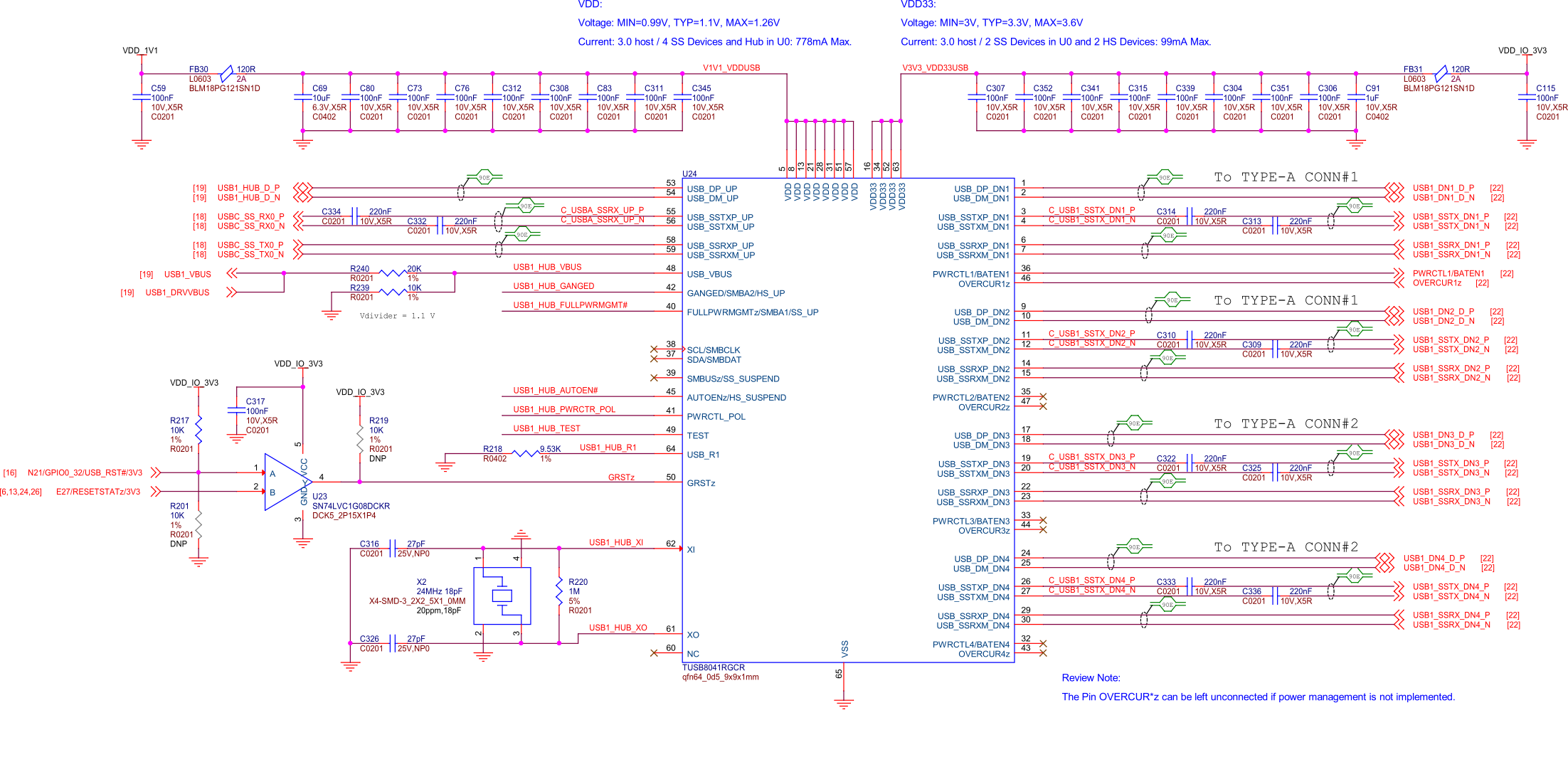
Fig. 71 BeagleY-AI USB3 hub#
BeagleY-AI features a USB3.1 HUB that provides 4 total USB3.1 Ports from a single USB3.1 Gen-1 (5 Gbps) SERDES0 lane.
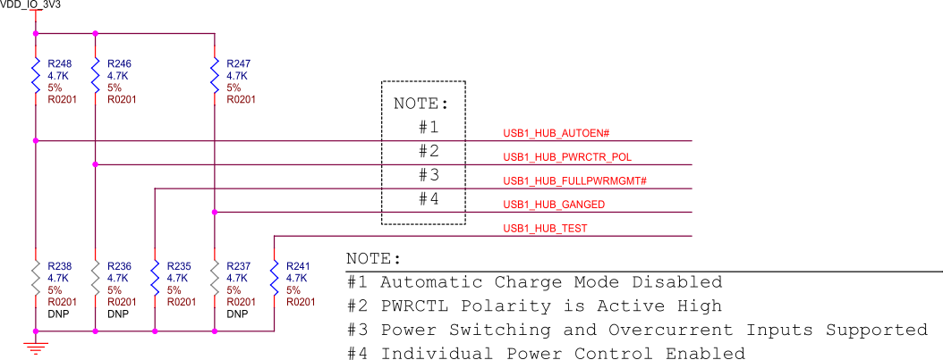
Fig. 72 BeagleY-AI USB hub config#
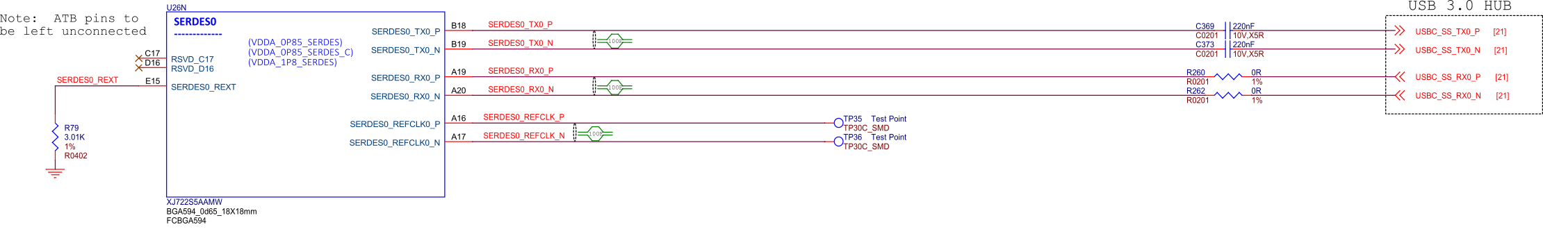
Fig. 73 BeagleY-AI SoC SERDES0#
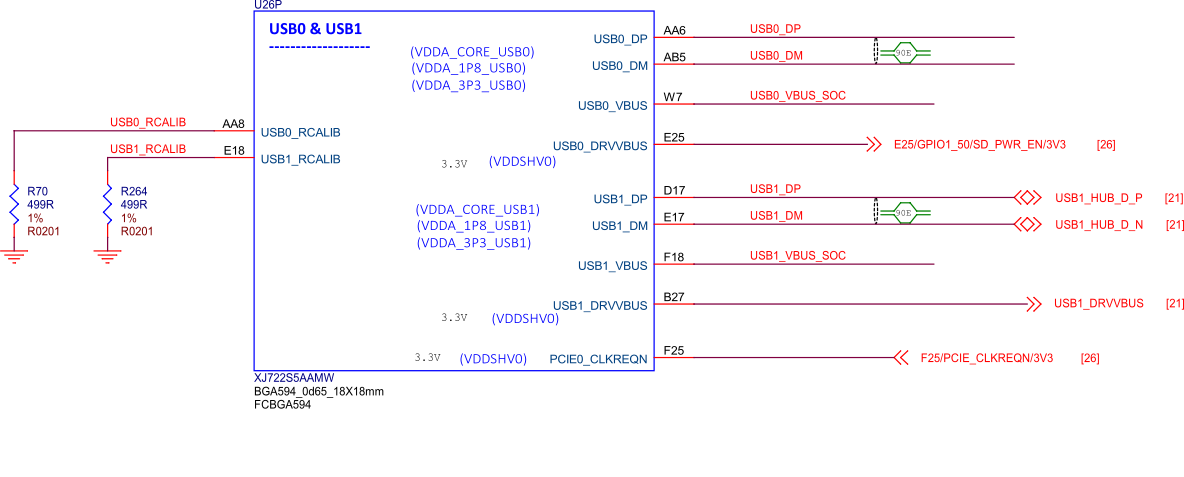
Fig. 74 BeagleY-AI SoC USB0 and USB1#
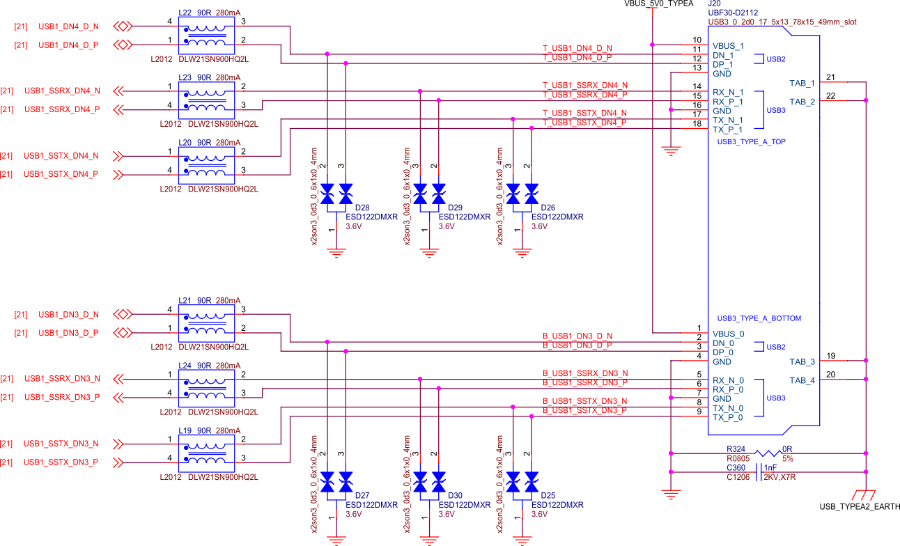
Fig. 75 BeagleY-AI USB-A Connector 1#
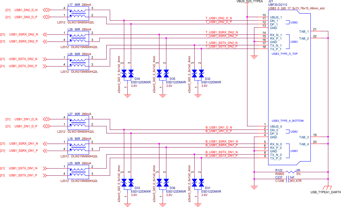
Fig. 76 BeagleY-AI USB-A Connector 2#
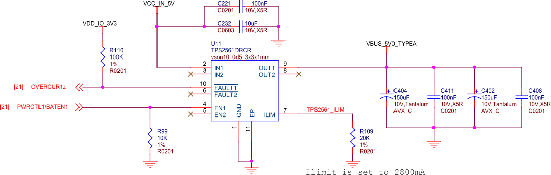
Fig. 77 BeagleY-AI dual USB current limiter#
BeagleY-AI features a dedicated USB current limiter that will prevent the Type-A ports from drawing power in excess of 2.8A.
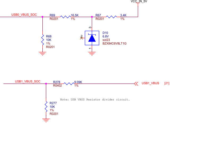
Fig. 78 BeagleY-AI USB VBUS resistor divider circuit#
PCI Express#
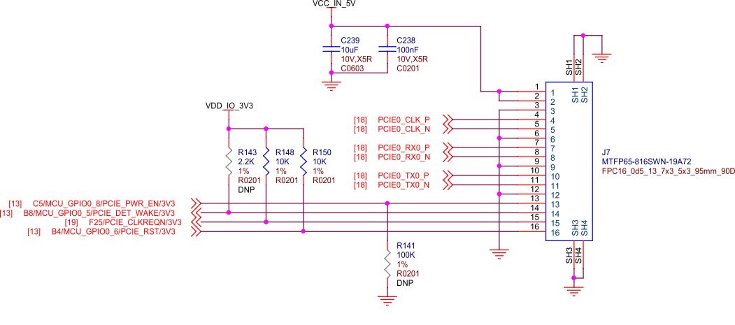
Fig. 79 BeagleY-AI PCIE connector#
BeagleY-AI features an RPi 5 compatible PCIe connector rated for PCIe Gen2 x1 (5GT/s) connected to SERDES1 on AM67A.
Note
Just like the Raspberry Pi 5, while the AM67A SoC is capable of PCIe Gen3 (8GT/s), the choice of cable/connector means that some devices may not be able to run at full Gen 3 speeds and will need to be limited to Gen 2 for stable operation.
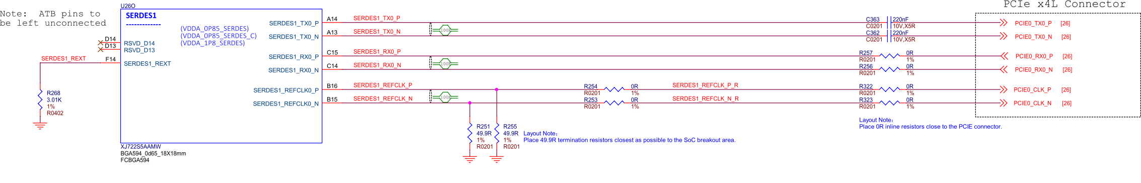
Fig. 80 BeagleY-AI SoC SERDES1#
RTC (Real-time Clock)#
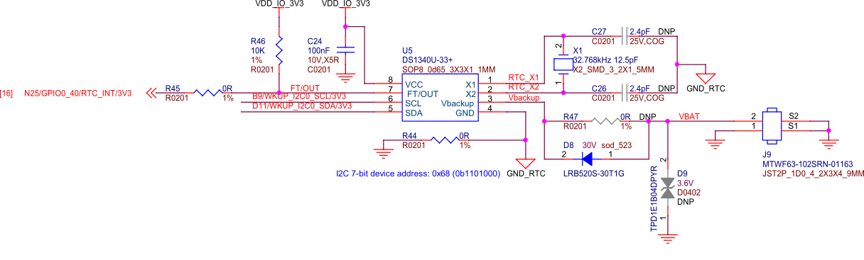
Fig. 81 BeagleY-AI I2C ext RTC#
BeagleY-AI has an on-board I2C RTC that can be powered by an external RTC for accurate time-keeping even when the board is powered off. For more information, see the corresponding docs page - Using the on-board Real Time Clock (RTC)
Fan Header#
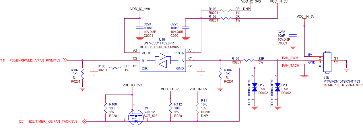
Fig. 82 BeagleY-AI fan connector#
BeagleY-AI features a Raspberry Pi 5 compatible Fan connector. The fan is software PWM controller in Linux by default to maintain a balance between cooling and noise depending on SoC temperature.
Networking#
WiFi / Bluetooth LE#
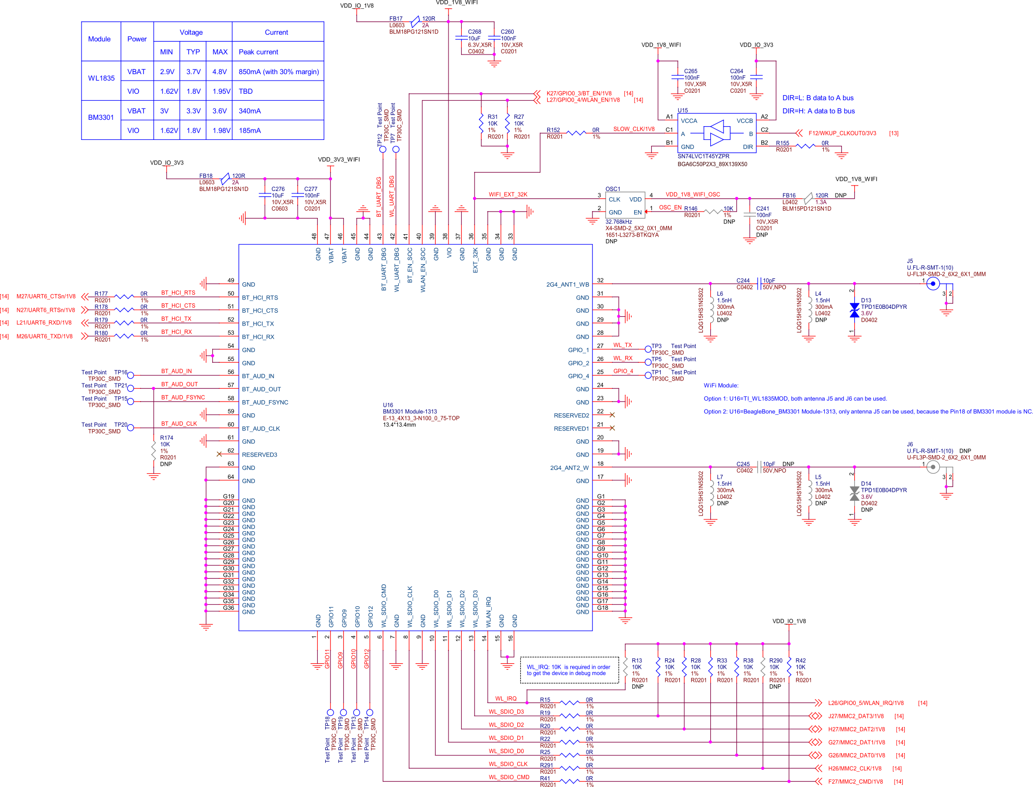
Fig. 83 BeagleY-AI WiFi module#
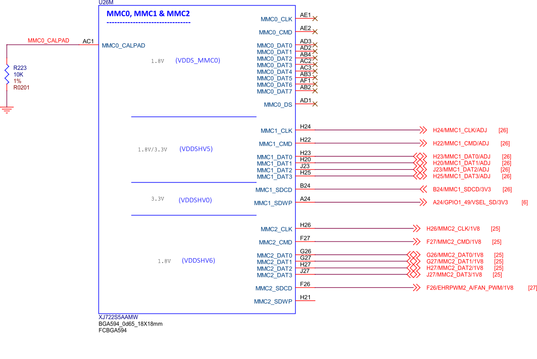
Fig. 84 BeagleY-AI SoC MMC0, MMC1, and MMC2#
BeagleY-AI features a Beagle BM3301 Wireless module based on the Texas Instruments CC3301 which features 2.4Ghz WiFi6 (802.11AX) and BLE 5.4
Note
5Ghz WiFi Bands and Bluetooth Classic are not supported by the CC3301.
Ethernet#
BeagleY-AI is equipped with a 1 Gb (10/100/1000) DP83867 Ethernet PHY connected over RGMII.
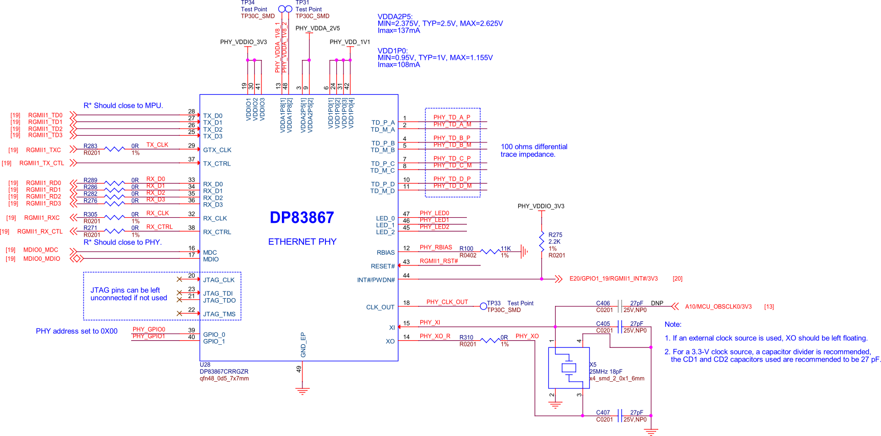
Fig. 85 BeagleY-AI ethernet DP83867#
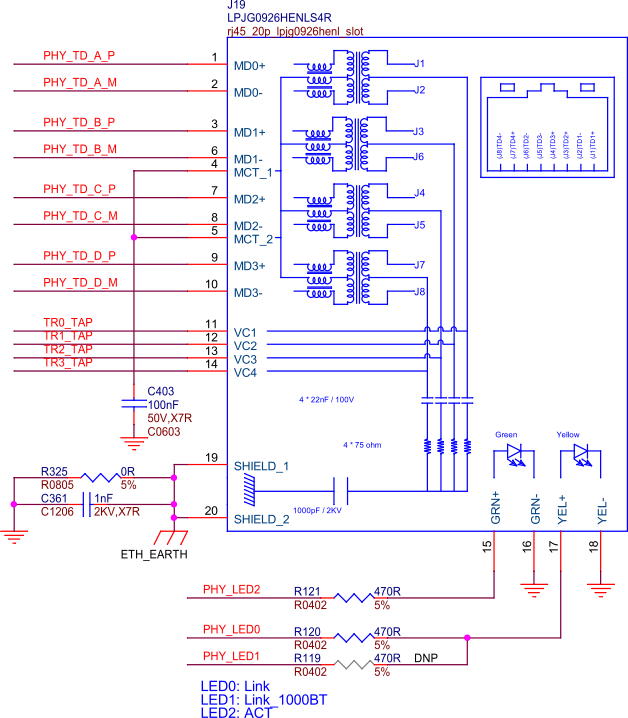
Fig. 86 BeagleY-AI ethernet connector#
BeagleY-AI uses an RJ45 ethernet connector with integrated magnetics.
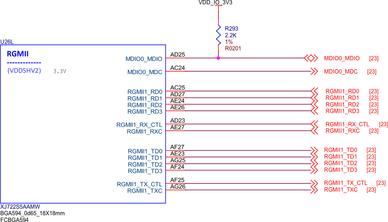
Fig. 87 BeagleY-AI SoC RGMII#
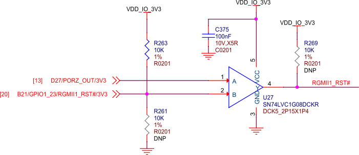
Fig. 88 BeagleY-AI SoC RGMII1 RST#
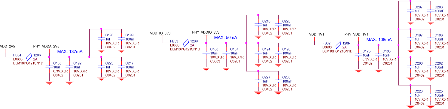
Fig. 89 BeagleY-AI Ethernet PHY caps#
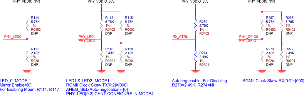
Fig. 90 BeagleY-AI Ethernet PHY misc#
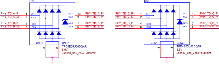
Fig. 91 BeagleY-AI Ethernet PHY protection#
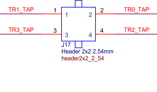
Fig. 92 BeagleY-AI PoE header#
Optional PoE (Power over Ethernet) can also be used with compatible 3rd party HATs designed for the Raspberry Pi 5.
Note
Only Pi 5 PoE HATs are compatible, as Pi 4 and previous designs have the PoE pins in a different location.
Cameras & Displays#
BeagleY-AI is capable of driving up to 3 Displays (HDMI, OLDI/LVDS & DSI) simultaneously.
HDMI via DPI Converter up to 1920 x 1080 @60FPS
OLDI/LVDS up to 3840 x 1080 @60FPS (Dual Link, 150-Mhz Pixel Clock)
DSI up to 3840 x 1080 at 60fps (4 Lane MIPI® D-PHY, 300-MHz Pixel Clock)
It also features 2 CSI interfaces and can support up to 8 Cameras using Virtual Channels and V3Link.
Note
The CSI1/DSI0 22-pin port is muxed between the two interfaces like the RPi 5, meaning that you must chose if it’s used as a Display or Camera port. The CSI0 22-pin connector can only be used as a Camera port.
HDMI (DPI)#
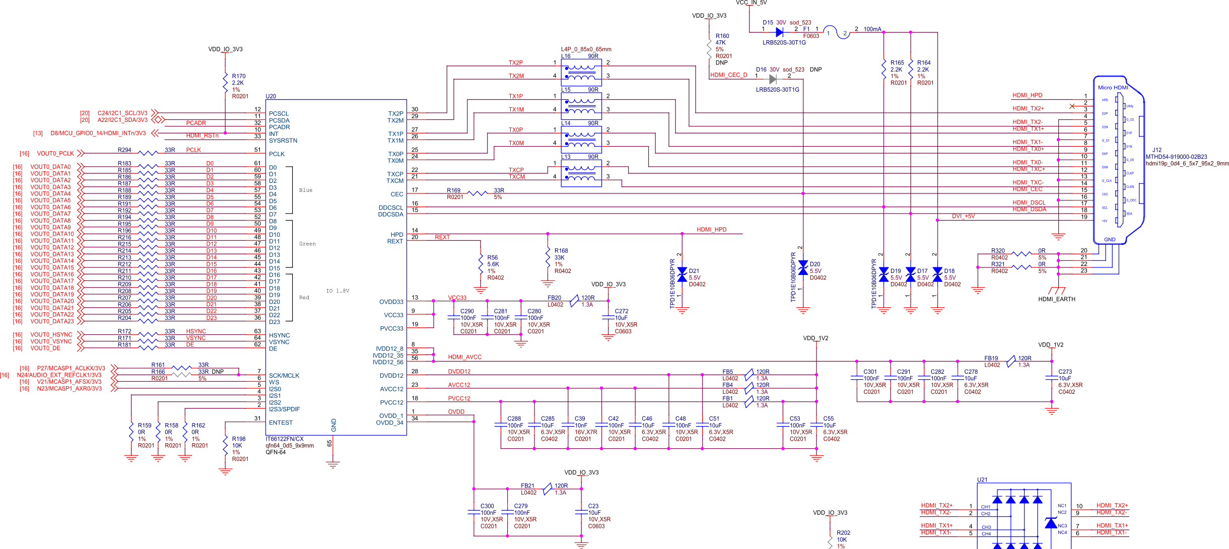
Fig. 93 BeagleY-AI RGB888 to HDMI#
BeagleY-AI has a single HDMI 1.4 port capable of up to 1080p @60FPS with Audio. This is achieved using an external Parallel RGB (DPI) to HDMI converter from ITE.
Because the DPI interface is used up by the HDMI converter, it does mean that DPI is not available on the 40Pin GPIO header.
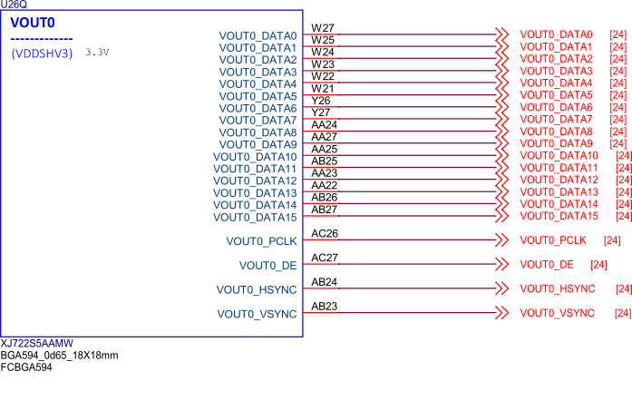
Fig. 94 BeagleY-AI SoC VOUT#
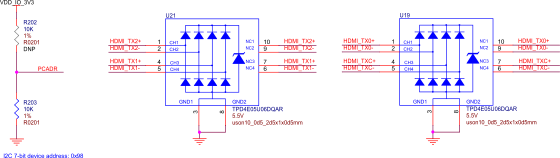
Fig. 95 BeagleY-AI HDMI addr protection#
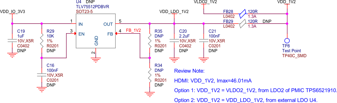
Fig. 96 BeagleY-AI HDMI power#
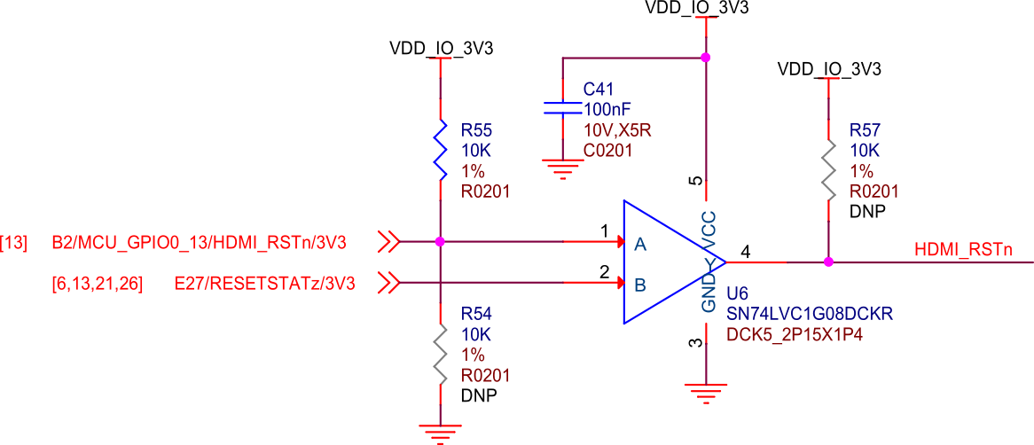
Fig. 97 BeagleY-AI HDMI reset#
OLDI (LVDS)#
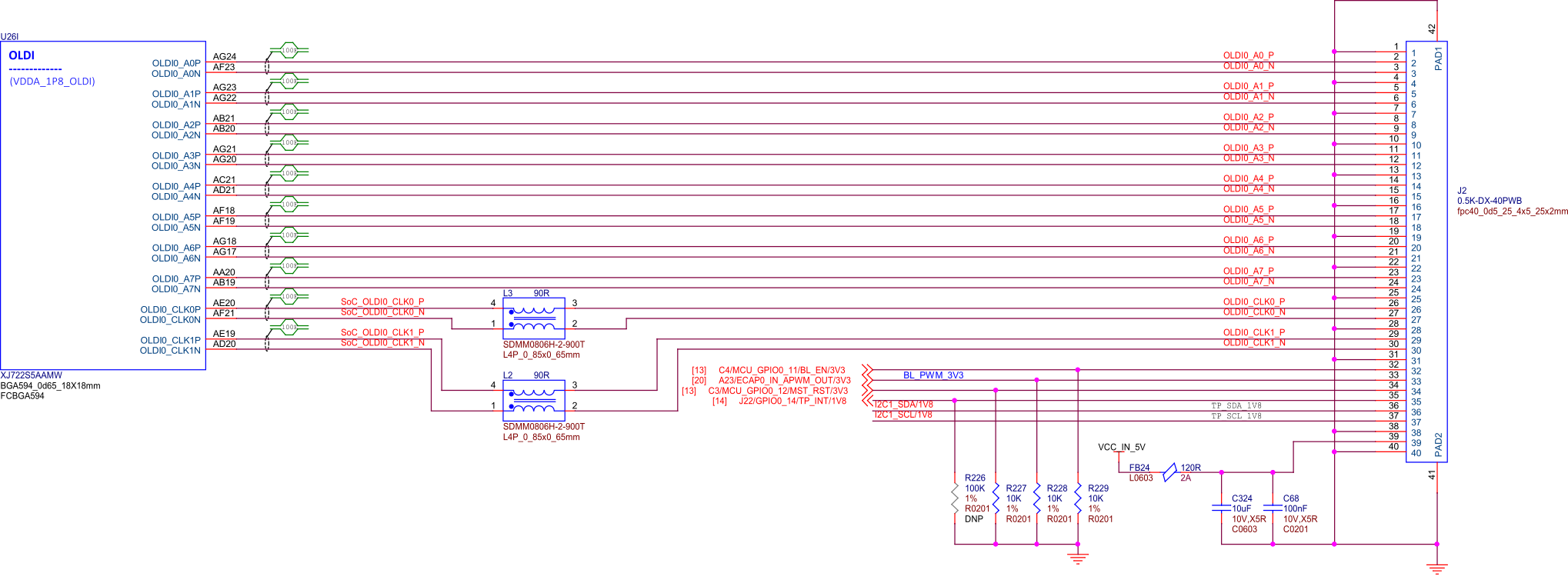
Fig. 98 BeagleY-AI SoC OLDI#
The OLDI connector on BeagleY-AI has the same pinout as the one used by Beagle Play, meaning the same displays are compatible.
DSI#
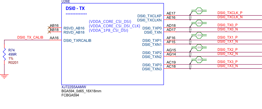
Fig. 99 BeagleY-AI SoC DSI0 TX connections#
The DSI0 port is shared withe CSI1 and selectable via a MUX switch to maintain Pi functionality. It features the same pinout found on the 22-pin DSI connector on RPi5 and BeagleBone AI-64 and enables connectivity to existing supported DSI displays.
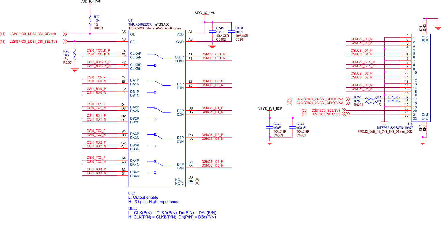
Fig. 100 BeagleY-AI RPI DSI/CSI#
Please note that DSI is only available on the second of the two 22-pin “CSI” connectors.
CSI#
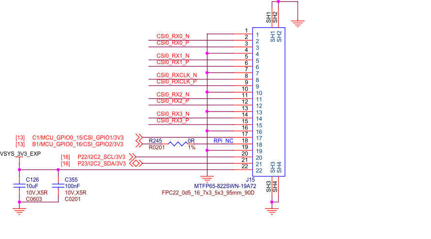
Fig. 101 BeagleY-AI RPI CSI#
To maintain a Pi compatible form factor, BeagleY-AI only exposes 2 of the 4 physical CSI interfaces of the AM67A SoC. Each CSI interfaces is MIPI® CSI-2 v1.3 + MIPI® D-PHY 1.2 with 4 Data Lanes running at up to 2.5Gbps/lane. The interface also supports up to 16 Virtual Channels for multi-camera applications using FPDLink or V3Link.
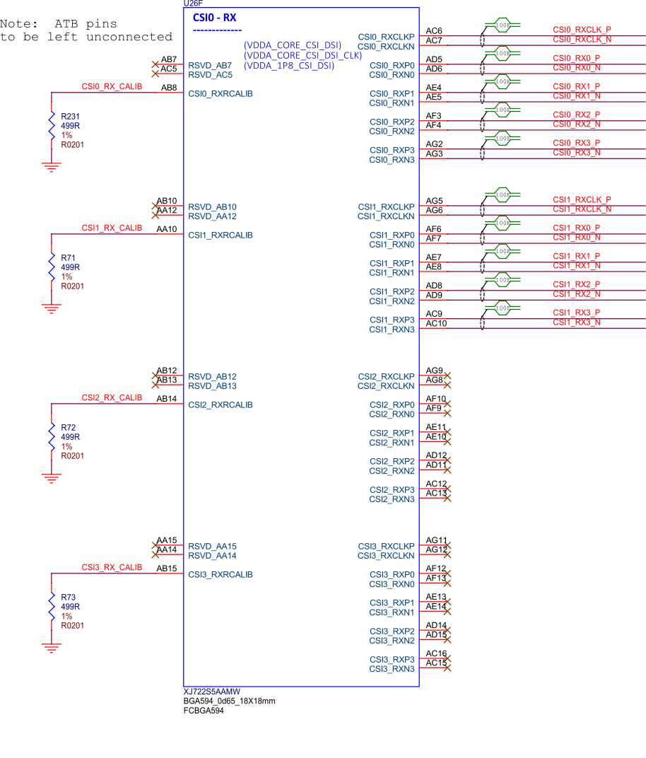
Fig. 102 BeagleY-AI SoC CSI1, CSI2, and CSI3#
Buttons and LEDs#
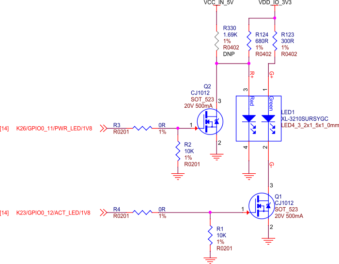
Fig. 103 BeagleY-AI LEDs#
BeagleY-AI features a single dual-color (Red/Green) LED for Power/Status indication.
Debug Ports#
JTAG Tag-Connect#
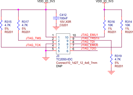
Fig. 104 BeagleY-AI Tag-Connect#
JTAG is available on the BeagleY-AI via a 10pin Tag-Connect header located on the bottom of the board between the USB 3.0 ports.
Because of the density of the board and tight fit of the USB connectors, the standard retention clip provided by Tag-Connect will not fit. A recommended 3D printable adapter is available on Printables
UART#
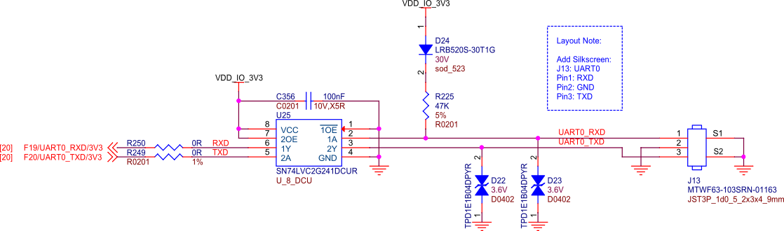
Fig. 105 BeagleY-AI debug UART port#
By default, BeagleY-AI exposes the UART port used by UBoot & Linux on a Pi Debugger compatible JST 3pin header. The UART port used for debug can also be changed in software to use a UART available on the 40Pin GPIO header.
PMIC NVM Tag-Connect#
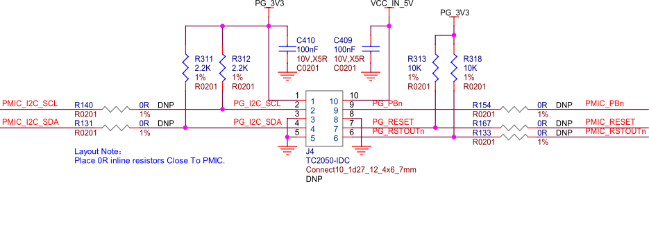
Fig. 106 BeagleY-AI PMIC NVM programming interface#
A PMIC programming header is present on the BeagleY-AI in the form of a 10pin Tag-Connect header located on the bottom of the board between the Ethernet and USB 3.0 ports. Ensure you do not connect JTAG to this port as the pinout and interface is different. PMIC NVM programming should not be performed unless you know what you’re doing. The port is mainly intended for use during manufacturing.
Miscellaneous#
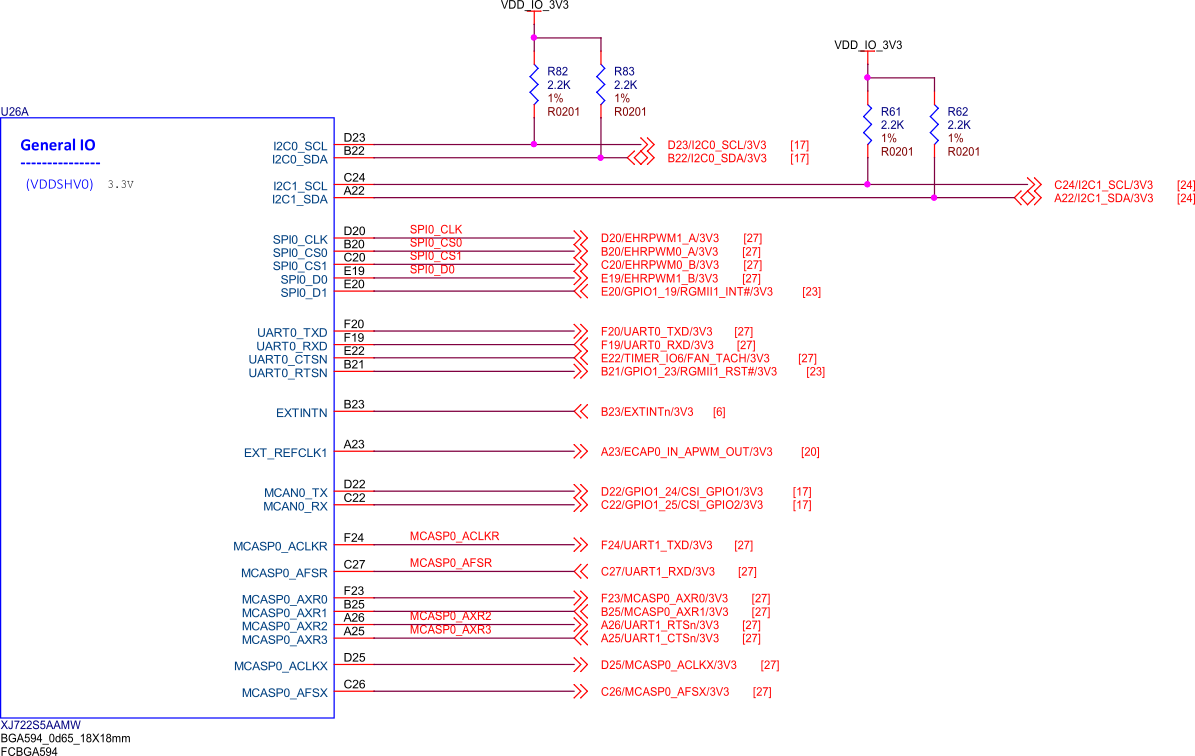
Fig. 107 BeagleY-AI general IO#
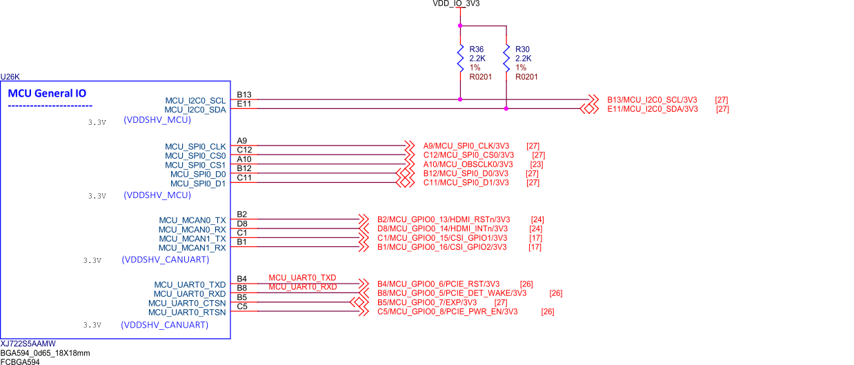
Fig. 108 BeagleY-AI MCU general IO#
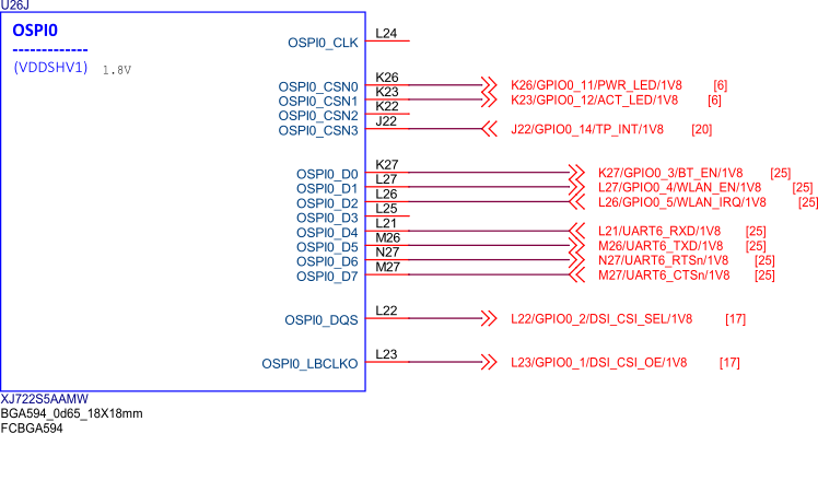
Fig. 109 BeagleY-AI SoC OSPI0#
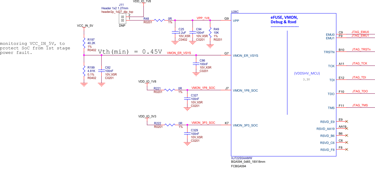
Fig. 110 BeagleY-AI SoC eFUSE, VMON, Debug, and RSVD#
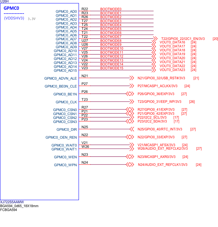
Fig. 111 BeagleY-AI SoC GPMC0#
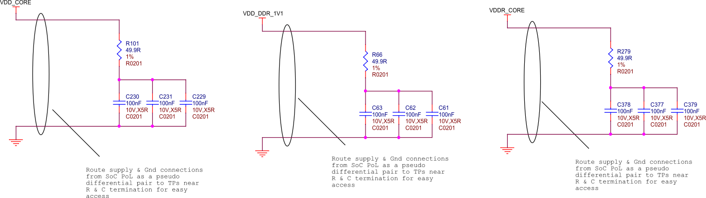
Fig. 112 BeagleY-AI SoC supply noise kelvin sensing#
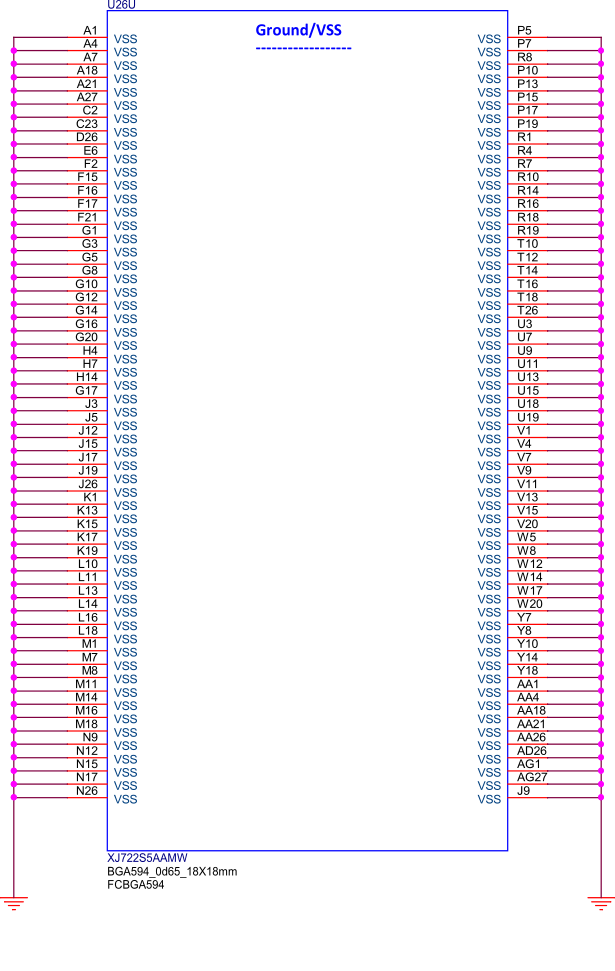
Fig. 113 BeagleY-AI SoC ground connections#
Mechanical Specifications#
Parameter |
Value |
|---|---|
Size |
85 x 56 x 20 mm |
Max heigh |
20mm |
PCB Size |
85 x 56 mm |
PCB Layers |
14 layers |
PCB Thickness |
1.6mm |
RoHS compliant |
Yes |
Gross Weight |
110 g |
Net Weight |
50 g |
