Using I2C ADC#
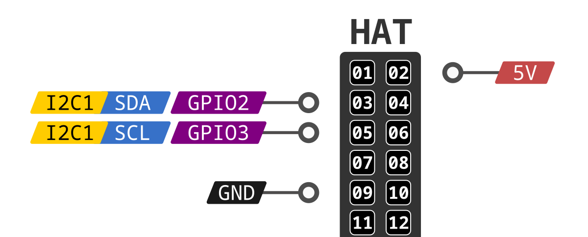
Using I2C device on BeagleY-AI is similar to using it on any Raspberry Pi compatible board. The image below shows the BeagleY-AI I2C pinout when using 5V for device VCC. For more information check pinout.beagley.ai/pinout/i2c.

Fig. 149 BeagleY-AI I2C pinout (5V)#
ADS1115 16-bit ADC#
Wiring/connection#
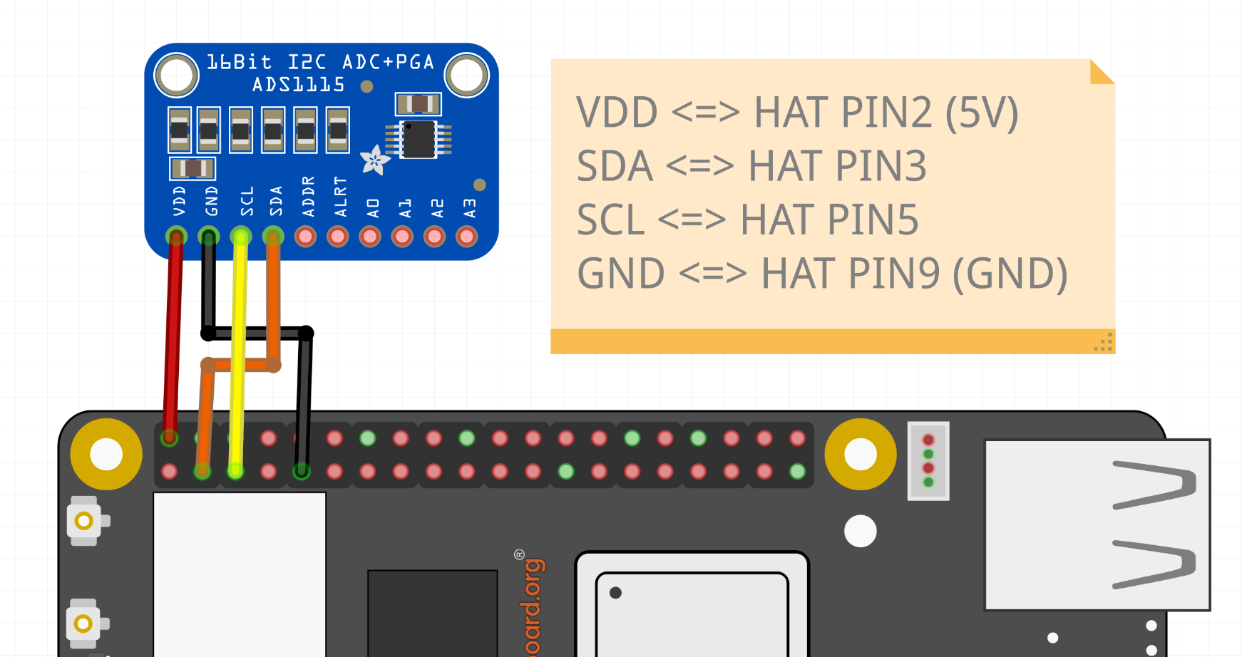
Following the I2C pinout shown above let’s make the connection of our ADS1115 ADC.

Fig. 150 ADS1115 connection#
Tip
The ADC can work on 2.0V - 5.5V voltage range, here we have selected to run it on 5V from HAT PIN2. For more information checkout ADS1115 datasheet.
To check if your ADS1115 ADC is correctly connected to your BeagleY-AI you can use i2cdetect command as shown below.
i2cdetect -y -r 1
The above command should show 48 address occupied in the output, which is the default I2C address of our ADS1115 ADC.
debian@BeagleBone:~$ i2cdetect -y -r 1
    0  1  2  3  4  5  6  7  8  9  a  b  c  d  e  f
00:                         -- -- -- -- -- -- -- --
10: -- -- -- -- -- -- -- -- -- -- -- -- -- -- -- --
20: -- -- -- -- -- -- -- -- -- -- -- -- -- -- -- --
30: -- -- -- -- -- -- -- -- -- -- -- -- -- -- -- --
40: -- -- -- -- -- -- -- -- 48 -- -- -- -- -- -- --
50: -- -- -- -- -- -- -- -- -- -- -- -- -- -- -- --
60: -- -- -- -- -- -- -- -- -- -- -- -- -- -- -- --
70: -- -- -- -- -- -- -- --
ADC Parameters#
PGA#
The pga is the programmable gain amplifier (values are full scale), in the device tree overlay we have ti,gain = <#>; where # can be following,
0: +/- 6.144 V1: +/- 4.096 V (default)2: +/- 2.048 V3: +/- 1.024 V4: +/- 0.512 V5: +/- 0.256 V
Data rate#
The data_rate in samples per second, in the device tree overlay we have ti,datarate = <#>; where # can be following,
0: 81: 162: 323: 644: 1285: 2506: 4757: 860 (default)
ADC Inputs#
The inputs can be made available by 8 sysfs input files in0_input - in7_input,
in0: Voltage over AIN0 and AIN1.in1: Voltage over AIN0 and AIN3.in2: Voltage over AIN1 and AIN3.in3: Voltage over AIN2 and AIN3.in4: Voltage over AIN0 and GND.in5: Voltage over AIN1 and GND.in6: Voltage over AIN2 and GND.in7: Voltage over AIN3 and GND.
Note
In the device tree overlay we have channel@4 - channel@7 device tree nodes representing in4 - in7 from the list above.
Using kernel driver#
To use the kernel driver to drive the ADS1115 ADC, we have created an overlay /boot/firmware/overlays/k3-am67a-beagley-ai-i2c1-ads1115.dtbo.
To load the overlay you have to add fdtoverlays /overlays/k3-am67a-beagley-ai-i2c1-ads1115.dtbo to /boot/firmware/extlinux/extlinux.conf as shown below.
...
...
...

label microSD (default)
kernel /Image
append console=ttyS2,115200n8 root=/dev/mmcblk1p3 ro rootfstype=ext4 resume=/dev/mmcblk1p2 rootwait net.ifnames=0 quiet
fdtdir /
fdt /ti/k3-am67a-beagley-ai.dtb
fdtoverlays /overlays/k3-am67a-beagley-ai-i2c1-ads1115.dtbo
After rebooting the board you should see /sys/bus/iio/devices/iio:device0 available.
debian@BeagleBone:~$ ls /sys/bus/iio/devices/ | grep iio
iio:device0
To show all the ADC Inputs you can create a script called adcreader.sh.
Create the file,
nano adcreader.sh
Copy and paste the content below,
in0=$(cat /sys/bus/iio/devices/iio\:device0/in_voltage0-voltage1_raw)
in1=$(cat /sys/bus/iio/devices/iio\:device0/in_voltage0-voltage3_raw)
in2=$(cat /sys/bus/iio/devices/iio\:device0/in_voltage1-voltage3_raw)
in3=$(cat /sys/bus/iio/devices/iio\:device0/in_voltage2-voltage3_raw)
in4=$(cat /sys/bus/iio/devices/iio\:device0/in_voltage0_raw)
in5=$(cat /sys/bus/iio/devices/iio\:device0/in_voltage1_raw)
in6=$(cat /sys/bus/iio/devices/iio\:device0/in_voltage2_raw)
in7=$(cat /sys/bus/iio/devices/iio\:device0/in_voltage3_raw)

echo "in0=${in0}\nin1=${in1}\nin2=${in2}\nin3=${in3}\nin4=${in4}\nin5=${in5}\nin6=${in6}\nin7=${in7}"
To allow the execution of the script as normal user use the command below,
chmod +x adcreader.sh
To view the ADC updates every 100ms use the
watchcommand as shown below,
watch -n 0.1 adcreader.sh
The above command should show the values as shown below and it will update them every 0.1s,
Every 0.1s: adcreader1.sh

in0=0
in1=-2
in2=2
in3=0
in4=4447
in5=4762
in6=4470
in7=4696
